
Page 55 - Read Online
P. 55
Sun et al. Intell Robot 2022;2(4):35570 I http://dx.doi.org/10.20517/ir.2022.23 Page 361
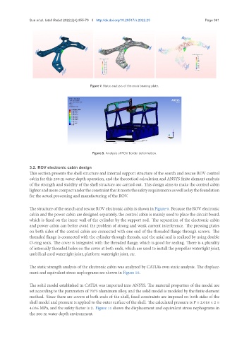
Figure 7. Static analysis of the main bearing plate.
Figure 8. Analysis of ROV border deformation.
3.2. ROV electronic cabin design
This section presents the shell structure and internal support structure of the search and rescue ROV control
cabin for this 200 m water depth operation, and the theoretical calculation and ANSYS finite element analysis
of the strength and stability of the shell structure are carried out. This design aims to make the control cabin
lighterandmorecompactundertheconstraintthatitmeetsthesafetyrequirementsaswellaslaythefoundation
for the actual processing and manufacturing of the ROV.
The structure of the search and rescue ROV electronic cabin is shown in Figure 9. Because the ROV electronic
cabin and the power cabin are designed separately, the control cabin is mainly used to place the circuit board,
which is fixed on the inner wall of the cylinder by the support rod. The separation of the electronic cabin
and power cabin can better avoid the problem of strong and weak current interference. The pressing plates
on both sides of the control cabin are connected with one end of the threaded flange through screws. The
threaded flange is connected with the cylinder through threads, and the axial seal is realized by using double
O-ring seals. The cover is integrated with the threaded flange, which is good for sealing. There is a plurality
of internally threaded holes on the cover at both ends, which are used to install the propeller watertight joint,
umbilical cord watertight joint, platform watertight joint, etc.
The static strength analysis of the electronic cabin was analyzed by CATIA’s own static analysis. The displace-
ment and equivalent stress nephograms are shown in Figure 10.
The solid model established in CATIA was imported into ANSYS. The material properties of the model are
set according to the parameters of 7075 aluminum alloy, and the solid model is modeled by the finite element
method. Since there are covers at both ends of the shell, fixed constraints are imposed on both sides of the
shell model and pressure is applied to the outer surface of the shell. The calculated pressure is P = 2.018 × 2 =
4.036 MPa, and the safety factor is 2. Figure 11 shows the displacement and equivalent stress nephograms in
the 200 m water depth environment.