
Page 9 - Read Online
P. 9
Page 102 Wu. Intell Robot 2021;1(2):99-115 I http://dx.doi.org/10.20517/ir.2021.11
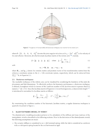
Figure 2. The quarter of the reachable and dexterous workspace (red volume) for the robotic arm.
[ ] [ ]
¤ ¤ ¤ ¤ ¤ 5 denotes the joint angular velocities and v = is the velocity of
¤
where = 1 2 3 4 ¤ q
the end-effector. Moreover, J is the kinematic Jacobian matrix of the robotic arm [40] , namely,
[ ]
[ ] z −1
J = j 1 j 2 j 3 j 4 j 5 where j = (4)
p −1 × z −1
with
z −1 = R −1 k; p −1 = q −1 − q (5)
where R −1 and q −1 denote the rotation matrix and position vector of the transformation matrix from the
reference coordinate system to the ( − 1)th coordinate system, respectively, which can be extracted from
∏
−1 −1 A in Equation (1).
=0
2.3. Dexterous workspace
The reachable workspace of the robotic arm can be visualized by considering the limitation of the joint dis-
placements and link dimensions. To effectively perform the kinematic performance, a dexterous workspace
is defined, throughout which the inverse of the condition number of the Jacobian matrix is greater than 0.2,
namely (J) ≥ 0.2. Since the Jacobian matrix of Equation (4) is not homogeneous, a characteristic length [41]
−1
is introduced to normalize the Jacobian matrix as follows:
[ ] 5
1 ∑
z −1 2 2
0
j = p −1 × z −1 / ; = kp −1 × z −1 k (6)
5
=1
By constraining the condition number of the kinematic Jacobian matrix, a regular dexterous workspace is
quarterly visualized in Figure 2.
3. ELASTODYNAMIC MODEL OF ROBOT
The elastodynamic modeling procedure pertains to the calculation of the stiffness and mass matrices of the
manipulator, which is described in the following sections. Prior to the derivation of the elastodynamic model,
the following assumptions are made:
• The actuator stiffness is considered as an 1-dof torsional spring, while the link is considered as cantilever
with a 6-dof spatial spring located at the end but treated as rigid.