Page 10 - Read Online
P. 10

Wu. Intell Robot 2021;1(2):99-115  I http://dx.doi.org/10.20517/ir.2021.11          Page 103


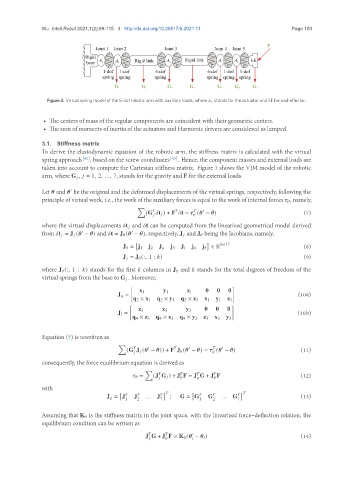
                 Figure 3. Virtual spring model of the 5-dof robotic arm with auxiliary loads, where       stands for the actuator and EE for end-effector.


                • The centers of mass of the regular components are coincident with their geometric centers.
                • The sum of moments of inertia of the actuators and Harmonic drivers are considered as lumped.

               3.1.  Stiffness matrix
               To derive the elastodynamic equation of the robotic arm, the stiffness matrix is calculated with the virtual
               spring approach [42] , based on the screw coordinates [43] . Hence, the component masses and external loads are
               taken into account to compute the Cartesian stiffness matrix. Figure 3 shows the VJM model of the robotic
               arm, where G    ,    = 1, 2, ..., 7, stands for the gravity and F for the external loads.


               Let    and    be the original and the deformed displacements of the virtual springs, respectively, following the
                         0
               principle of virtual work, i.e., the work of the auxiliary forces is equal to the work of internal forces      , namely,
                                               ∑
                                                                      0
                                                  (G   t    ) + F   t =    (   −   )                   (7)
                                                                    
                                                       
               where the virtual displacements   t    and   t can be computed from the linearized geometrical model derived
               from   t    = J    (   −   ) and   t = J    (   −   ), respectively, J    and J    being the Jacobians, namely,
                                             0
                             0
                                               [                       ]   6×17
                                          J    = j 1  j 2  J     j 3  J     j 4  j 5 ∈ R               (8)
                                          J    = J    (:, 1 :   )                                      (9)
               where J    (:, 1 :   ) stands for the first    columns in J    and    stands for the total degrees of freedom of the
               virtual springs from the base to G    . Moreover,
                                             [                                 ]
                                                x 1     y 1     z 1   0   0   0
                                         J    =                                                       (10a)
                                              q 2 × x 1  q 2 × y 1  q 2 × z 1  x 1  y 1  z 1
                                             [                                 ]
                                                z 3     x 3     y 3   0   0   0
                                         J    =                                                      (10b)
                                              q 4 × z 3  q 4 × x 3  q 4 × y 3  z 3  x 3  y 3

               Equation (7) is rewritten as
                                         ∑
                                                   0             0           0
                                            (G J    (   −   )) + F J    (   −   ) =    (   −   )      (11)
                                                                           
                                                
               consequently, the force equilibrium equation is derived as
                                                  ∑


                                                    =  (J G    ) + J F = J G + J F                    (12)


               with
                                         [                 ]      [                  ]   
                                     J    = J  J  ... J   ;   G = G    G    ... G                     (13)
                                           1   2       7            1    2       7
               Assuming that K    is the stiffness matrix in the joint space, with the linearized force–deflection relation, the
               equilibrium condition can be written as
                                                                  0
                                                  J G + J F = K    (   −       )                      (14)


   5   6   7   8   9   10   11   12   13   14   15