Page 53 - Read Online
P. 53

Lekbir et al. Energy Mater. 2025, 5, 500101  https://dx.doi.org/10.20517/energymater.2025.46  Page 5 of 17

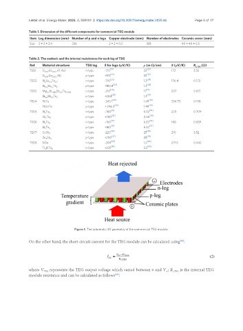
               Table 1. Dimension of the different components for commercial TEG module
                Item Leg dimension (mm) Number of p and n legs Copper electrode (mm) Number of electrodes Ceramic cover (mm)
                Size  2 × 2 × 3.4   256               2 × 2 × 0.3        128              40 × 40 × 0.5


               Table 2. The seebeck and the internal resistances for each leg of TEG
                Ref   Material structure   TEG leg  S for legs (μV/K)  ρ (m Ω/cm)    S (μV/K)   R s,TEG  (Ω)
                                                       [21]              [22]
                TEG1  Si  Ge   (P, As)     n-type   -173               25            173        3.32
                       0.97  0.03
                                                       [21]              [22]
                      Si 0.97 Ge 0.03  (B)  p-type  +173               25
                TEG2  Bi Se Te 2.7         n-type   -170 [23]          1.3 [24]      176.4      0.173
                         0.3
                       2
                                                        [25]             [24]
                      Bi Sb Te 3           p-type   +182.8             1.3
                          1.5
                       0.5
                TEG3  Mg Bi 1.498 Sb Te 0.002  n-type  -210 [26]       11 [27]       207        0.817
                              0.5
                        3.2
                                                        [28]             [24]
                      Bi Sb Te             p-type   +204               1.3
                       0.4  1.6  3
                TEG4  PbTe                 n-type   -343.1 [29]        1.49 [30]     294.73     0.198
                                                         [29]             [30]
                      PbSnTe               p-type   + 246.3            1.49
                TEG5  Bi Te 3              n-type   −160 [31]          6.32 [32]     220        0.709
                       2
                      Sb Te 3              p-type   +280 [33]          4.36 [34]
                       2
                                                       [31]               [32]
                TEG6  Bi Te                n-type   −160               6.32          160        0.839
                       2  3
                                                       [31]               [32]
                      Bi Te 3              p-type   +160               6.32
                       2
                                                       [35]              [36]
                TEG7  CoSb                 n-type   -220               25            210        3.52
                         3
                                                        [37]             [38]
                      Zn Sb 3              p-type   +200               28
                       4
                TEG8  SiGe                 n-type   -200 [39]          1.2 [40]      217.5      0.442
                                                       [41]              [41]
                      Tl BiTe              p-type   +235               5.5
                       9  6


                                     Figure 1. The schematic 3D geometry of the commercial TEG module.

               On the other hand, the short-circuit current for the TEG module can be calculated using :
                                                                                         [42]


               where V  represents the TEG output voltage which varied between 0 and V ; R s,TEG  is the internal TEG
                      TEG
                                                                                  oc
               module resistance and can be calculated as follows :
                                                         [43]
   48   49   50   51   52   53   54   55   56   57   58