
Page 84 - Read Online
P. 84
Chen et al. Energy Mater. 2025, 5, 500045 https://dx.doi.org/10.20517/energymater.2024.144 Page 11 of 27
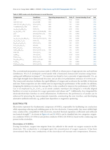
Table 4. SOEC anodes and cell performance in recent literature
Components Conditions Operating temperature/°C Volt./V Current density/A·cm -2 Ref.
LSM 50% H O/H 2 900 0.70 0.500 [72]
2
LSM-SDC-CuO 40 vol% RH 800 1.50 0.360 [73]
LSM-YSZ-SrTi Fe Co O 3-δ 50% H O/H 2 800 1.30 2.000 [74]
0.3
2
0.1
0.6
Y-stabilized Bi O -LSM 45% AH 800 1.28 1.520 [75]
2 3
La Sr Fe Mn O 3-δ 100% CO 2 850 2.00 1.744 [76]
0.4
0.1
0.6
0.9
La Sr FeO -YSZ 50% H O/25% H /N 2 800 1.30 0.660 [77]
3-δ
0.6
2
0.4
2
LSCF 63% H O/7% H /N 2 900 1.30 0.780 [78]
2
2
LSCF-GDC 80% H O/H 2 773 1.20 0.750 [79]
2
La Sr Co Fe Nb O 75% CO /15% H O/H 850 1.30 0.638 [80]
0.4 0.6 0.2 0.7 0.1 3-δ 2 2 2
La Sr Fe Ti O 3 100% CO 2 800 2.00 0.521 [81]
0.3
0.7
0.7
0.3
Ba Sr Co Fe O 50% H O/H 800 1.30 1.370 [82]
0.6 0.4 0.8 0.2 3 2 2
SrCo Fe Ga O 3-δ 40% AH 850 1.50 2.221 [83]
0.1
0.8
0.1
BaZr Co O 50% H O/H 800 1.30 1.430 [84]
0.2 0.8 3-δ 2 2
CaMn Nb O 3-δ 50% H O/3% H /N 2 700 1.70 0.210 [85]
2
0.1
0.9
2
SFM-YSZ 75% H O/H 750 1.20 0.327 [86]
2 2
La NiO 4+δ 21% H O/N 2 750 0.107 0.500 [87]
2
2
PrBaCo O 5+δ 90% CO /CO 750 1.30 0.750 [88]
2
2
Nd 1.95 Ba 0.05 NiO 4+δ pH O = 0.03 atm 750 1.60 1.210 [89]
2
Pr NiO 4+δ 50% H O/H 2 800 1.20 0.980 [90]
2
2
PrBaFe Co O 50% H O/CO 850 1.30 0.650 [45]
1.8 0.2 5+δ 2 2
The conventional preparation processes make it difficult to obtain pores of appropriate size and uniform
distribution. Wu et al. developed a novel anode with a biomimetic honeycomb structure using freeze-
casting and infiltration techniques . The material was found to have a porosity of approximately 75%, an
[92]
ultra-high-strength three-dimensional structure, and an ultra-low polarization resistance of 0.0094 Ω·cm .
2
The honeycomb structure facilitates the rapid diffusion of oxygen and accelerates the mobility of electrons
and ions. Nanocomposites are also widely used in improving the performance of the anodes. In addition,
designing the skeleton structure for easy gas flow is also a method to improve the performance of SOECs.
Cao et al. employed La Sr CoO as an anode catalytic nanolayer and designed a vertically aligned
0.4
3-δ
0.6
backbone structure to promote the oxygen generation and release rate . Additionally, they integrated the
[93]
electrode/electrolyte interface to avoid delamination. Furthermore, the performance of anodes can be
enhanced by preparing the nanocomposite materials, constructing the new interface, and developing
alternative synthesis methods, e.g., pulsed laser deposition or magnetron sputtering.
ELECTROLYTE
Electrolytes represent the fundamental component of SOECs, responsible for facilitating ion conduction
while separating reducing and oxidizing gases at the two electrodes. Consequently, they must exhibit high
ionic conductivity, compatibility with electrodes, matched thermal expansion coefficients and sufficient
mechanical strength . As shown in Figure 6A and B, SOECs can be classified into two categories: oxygen-
[94]
ion conductor SOECs (O-SOECs) and proton conductor SOECs (H-SOECs), based on the conducting ions
present in the electrolyte.
Electrolytes of O-SOECs
During electrolysis, oxygen ions migrate from the cathode to the anode via oxygen vacancies in the
electrolyte. The conductivity is contingent upon the concentration of oxygen vacancies. It has been
demonstrated that the ionic conductivity of the electrolytes will increase with temperatures. However,