
Page 36 - Read Online
P. 36
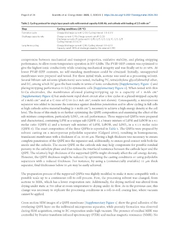
Page 8 of 24         Boaretto et al. Energy Mater. 2025, 5, 500040  https://dx.doi.org/10.20517/energymater.2024.203

               Table 2. Cycling protocol for single layer pouch cells with nominal capacity 0.08 Ah, and cathode with loading of 2.5 mAh cm -2
                Step                   Cycling conditions (25 °C)
                Formation cycle        Charge/discharge current: C/20; Cycling interval: 3.0-4.3 V
                Discharge capacity rate  Charge current: C/10; Charge current cut off: C/20
                                       Discharge currents (5 cycles each): C/10, C/5, C/3, C/2, 1C, C/3, C/5
                                       Cycling interval: 3.0-4.3 V
                Long-term cycling      Charge/discharge current: C/10; Cycling interval: 3.0-4.3 V
                                       Capacity cutoff: 80% of discharge capacity (1st value at C/10)


               compromise between mechanical and transport properties, oxidative stability, and plating stripping
               performance, to allow room-temperature operation in HV-LMBs. The PVdF-HFP content was optimized to
               give the highest ionic conductivity while retaining mechanical integrity and was finally set to 20 wt%. At
               lower PVdF-HFP contents, no self-standing membranes could be obtained. Initially, unsupported
               membranes were prepared and tested. For these initial trials, acetone was used as a processing solvent.
               Several lithium salt solvents (plasticizers) were tested, including PC, tetra(ethylene glycol)dimethyl ether,
               and EC, among which EC gave the best results in terms of ionic conductivity [Supplementary Figure 1] and
               plating/stripping performance in Li||Li symmetric cells [Supplementary Figure 2]. When tested with thin
               Li-Cu  electrodes,  the  membranes  allowed  plating/stripping  up  to  a  capacity  of  1  mAh  cm
                                                                                                         -2
               [Supplementary Figure 3] but underwent rapid short circuit after a few cycles at a plated/stripped capacity
               of 2 mAh cm  and at a C-rate of C/10 (0.2 mA cm , results not shown). Consequently, a microporous
                                                            -2
                          -2
               separator was added to increase the resistance against dendrites penetration and to allow cycling in full cells
               at high cathode active material loading (2-3 mAh cm ), necessary to achieve a high energy density at the cell
                                                           -2
               level. The focus of this study is on further optimizing the QSPE composition and examining the effect of the
               salt mixture composition, particularly LiNO , on cell performance. Three supported QSPEs were prepared
                                                     3
               and characterized, containing LiFSI as a unique salt (QSPE-1), a binary mixture of LiFSI and LiBOB in a 4:1
               molar ratio (QSPE-2) and a ternary salt mixture of LiFSI, LiBOB, and LiNO , in a 4:1:1 molar ratio
                                                                                     3
               (QSPE-3). The exact composition of the three QSPEs is reported in Table 1. The QSPEs were prepared by
               solvent casting on a microporous polyolefin separator (Celgard 2500), resulting in homogeneous,
               translucent membranes with a thickness of ca. 60-80 µm. Having a high thickness was necessary to ensure
               complete penetration of the QSPE into the separator and, additionally, to ensure good contact with both the
               anode and the cathode. The excess QSPE on the cathode side may help compensate for possible residual
               porosity in the catholyte phase and thus reduce the interfacial resistance between the cathode layer and the
               QSPE. The relatively high thickness of the supported QSPEs might obviously affect the cell energy density.
               However, the QSPE thickness might be reduced by optimizing the casting conditions or using polyolefin
               separators with a reduced thickness. For instance, by using a (commercially available) 15 µm thick
               separator, final thicknesses below 50 µm may be easily achieved.

               The preparation process of the supported QSPEs was slightly modified to make it more compatible with a
               possible scale-up to a continuous roll-to-roll process. First, the processing solvent was changed, from
               acetone to MEK, which has a lower evaporation rate. Additionally, the drying method was altered from
               drying under static at 500 mbar at room temperature to drying under Ar flow. As in the previous case, this
               change was necessary to replicate the processing conditions in a roll-to-roll coating line, where vacuum
               cannot be applied.

               Cross-section SEM images of a QSPE membrane [Supplementary Figure 4] show the good adhesion of the
               overlaying QSPE layer on the infiltrated microporous separator, while porosity formation was observed
               during SEM acquisition, owing to EC evaporation under high vacuum. The presence of residual MEK was
               controlled by Fourier transform infrared spectroscopy (FTIR) and nuclear magnetic resonance (NMR). No