
Page 69 - Read Online
P. 69
Page 20 of 30 Mazzapioda et al. Energy Mater 2023;3:300019 https://dx.doi.org/10.20517/energymater.2023.03
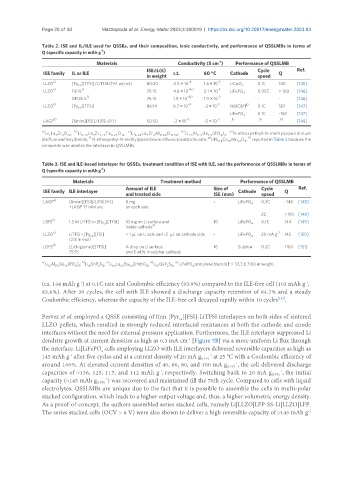
Table 2. ISE and IL/ILE used for QSSEs, and their composition, ionic conductivity, and performance of QSSLMBs in terms of
-1
Q (specific capacity in mAh g )
Materials Conductivity (S cm ) Performance of QSSLMB
-1
ISE:IL(E) Cycle Ref.
ISE family IL or ILE r.t. 60 °C Cathode Q
in weight speed
a) -4 -3
LLZO [Py ][TFSI]/LiTFSI (19:1 wt/wt) 80:20 4.0 × 10 1.6 × 10 LiCoO 0.1C 140 [145]
14 2
LLZO c) FSI IL e) 75:15 4.8 × 10 -4c) 2.1 × 10 -3 LiFePO 4 0.05C > 100 [146]
f) -4c) -3
DFOB IL 75:15 1.9 × 10 1.0 × 10 - - [146]
b) -4 -3 g)
LLZO [Py ][TFSI] 86:14 6.7 × 10 ~3 × 10 NMC811 0.1C 187 [147]
14
LiFePO 4 0.1C ~150 [147]
d) -3 -3 h) h) h)
LAGP [Bmim][FSI]/LiFSI (9:1) 50:50 ~2 × 10 ~5 × 10 - - - [148]
a) b) c) d) e)
Li La Zr O ; Li 6.75 La Zr 1.75 Ta 0.25 O ; Li 6.24 La Zr Al 0.24 O 11.98 ; Li 1.5 Al 0.5 Ge 1.5 (PO ) ; N-ethoxyethyl-N-methylpiperidinium
3
4 3
3
12
7
2
2
3
12
g)
f)
h)
bis(fluorosulfonyl)imide; N-ethoxyethyl-N-methylpiperidinium difluoro(oxalato)borate; LiNi Co Mn O ; reported in Table 3 because the
2
0.1
0.1
0.8
composite was used as the interlayer in QSSLMBs.
Table 3. ISE and ILE-based interlayer for QSSEs, treatment condition of ISE with ILE, and the performance of QSSLMBs in terms of
-1
Q (specific capacity in mAh g )
Materials Treatment method Performance of QSSLMB
Amount of ILE Size of Cycle Ref.
ISE family ILE interlayer Cathode Q
and treated side ISE (mm) speed
a)
LAGP [Bmim][FSI]/LiFSI (9:1) 8 mg - LiFePO 4 0.3C ~140 [148]
+LAGP 1:1 mixture on each side
2C > 110 [148]
LSPS b) 1.5 M LiTFSI in [Py ][TFSI] 10 mg on Li surface and 10 LiFePO 4 0.1C 144 [149]
13
inside cathode e)
LLZO c) LiTFSI - [Py ][FSI] < 1 µL on Li side and ~2 µL on cathode side - LiFePO 4 20 mA g -1 145 [150]
14
(2:8 in mol)
LGPS d) [Li(triglyme)][TFSI] A drop on Li surface 16 Sulphur 0.2C 1100 [151]
75:15 and 5 wt% in sulphur cathode
a) b) c) d) e)
Li Al Ge (PO ) ; Li SnP S ; Li La Ba ZrNbO ; Li GeP S ; LiFePO :acetylene black:ILE = 33.3:6.7:60 in weight.
6.5
2.5
10
2 12
12
0.5
4
1.5
2 12
4 3
10
0.5
1.5
(ca. 144 mAh g ) at 0.1C rate and Coulombic efficiency (93.9%) compared to the ILE-free cell (103 mAh g ,
-1
-1
83.6%). After 30 cycles, the cell with ILE showed a discharge capacity retention of 84.7% and a steady
Coulombic efficiency, whereas the capacity of the ILE-free cell decayed rapidly within 10 cycles .
[152]
Pervez et al. employed a QSSE consisting of thin [Pyr ][FSI]-LiTFSI interlayers on both sides of sintered
14
LLZO pellets, which resulted in strongly reduced interfacial resistances at both the cathode and anode
interfaces without the need for external pressure application. Furthermore, the ILE interlayer suppressed Li
-2
dendrite growth at current densities as high as 0.3 mA cm [Figure 7B] via a more uniform Li flux through
the interface. Li|LiFePO cells employing LLZO with ILE interlayers delivered reversible capacities as high as
4
-1
145 mAh g after five cycles and at a current density of 20 mA g (LFP) -1 at 25 °C with a Coulombic efficiency of
around 100%. At elevated current densities of 40, 60, 80, and 100 mA g (LFP) -1 , the cell delivered discharge
capacities of ≈136, 125, 117, and 112 mAh g , respectively. Switching back to 20 mA g (LFP) -1 , the initial
-1
capacity (≈145 mAh g (LFP) -1 ) was recovered and maintained till the 70th cycle. Compared to cells with liquid
electrolytes, QSSLMBs are unique due to the fact that it is possible to assemble the cells in multi-polar
stacked configuration, which leads to a higher output voltage and, thus, a higher volumetric energy density.
As a proof-of-concept, the authors assembled series stacked cells, namely Li|LLZO|LFP-SS-Li|LLZO|LFP.
-1
The series stacked cells (OCV > 8 V) were also shown to deliver a high reversible capacity of ≈145 mAh g