
Page 195 - Read Online
P. 195
Page 6 of 23 Yang et al. Energy Mater 2024;4:400061 https://dx.doi.org/10.20517/energymater.2023.144
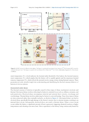
Figure 3. (A) DSC curves for different electrolytes. This figure is quoted with permission from Jiang et al. [61] (B) A typical ARC curve of a
commercial pouch cell. This figure is quoted with permission from Chen et al. [32] (C) Chain relationship diagrams for three abuse
conditions.
onset temperature (T ), which indicates the thermal safety threshold of the battery; the thermal runaway
1
onset temperature (T ), which implies that the battery will be rapidly ignited; and the maximum thermal
2
runaway temperature (T ), which reflects the internal reactive energy release during thermal runaway. These
3
parameters provide valuable insight into understanding and identifying the thermal runaway behavior of
batteries in various systems.
Assessment under abuse
The thermal runaway of batteries is typically caused by three types of abuse: mechanical, electrical, and
thermal. Mechanical abuse involves subjecting the battery to external forces such as collision, extrusion, and
nail penetration. Electrical abuse encompasses internal and external short-circuits, overcharge and
overdischarge. Thermal abuse involves subjecting the battery to external heating. These three types of abuse
are interconnected rather than mutually exclusive, as shown in Figure 3C. Mechanical abuse can lead to
electrical abuse, specifically through damage to the battery’s interior due to external stresses, resulting in an
internal short-circuit. Subsequently, electrical abuse can result in thermal abuse. When a short-circuit
occurs within the battery, a significant amount of heat is generated, triggering chemical reactions at higher
temperatures and releasing even more heat. This is equivalent to the battery being continuously heated by