


Page 93 - Read Online
P. 93
Page 8 of 22                                                 Song et al. Energy Mater. 2026, 6, 600019


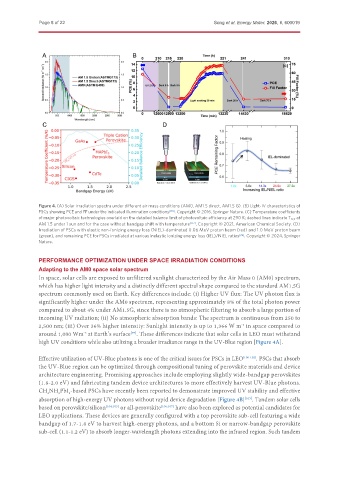
               Figure 4. (A) Solar irradiation spectra under different air mass conditions (AM0, AM1.5 direct, AM1.5 G). (B) Light-IV characteristics of
               PSCs showing PCE and FF under the indicated illumination conditions [103] . Copyright © 2016, Springer Nature. (C) Temperature coefficients
               of major photovoltaic technologies overlaid on the detailed balance limit of photovoltaic efficiency at 290 K; dashed lines indicate T PCE  at
               AM 1.5 under 1 sun and for the case without bandgap shift with temperature [117] . Copyright © 2021, American Chemical Society. (D)
               Irradiation of PSCs with elastic non-ionizing energy loss (NIEL)-dominated 0.06 MeV proton beam (red) and 1.0 MeV proton beam
               (green), and remaining PCE for PSCs irradiated at various inelastic ionizing energy loss (IEL)/NIEL ratios [26] . Copyright © 2024, Springer
               Nature.


               PERFORMANCE OPTIMIZATION UNDER SPACE IRRADIATION CONDITIONS
               Adapting to the AM0 space solar spectrum
               In space, solar cells are exposed to unfiltered sunlight characterized by the Air Mass 0 (AM0) spectrum,
               which has higher light intensity and a distinctly different spectral shape compared to the standard AM1.5G
               spectrum commonly used on Earth. Key differences include: (i) Higher UV flux: The UV photon flux is
               significantly higher under the AM0 spectrum, representing approximately 8% of the total photon power
               compared to about 4% under AM1.5G, since there is no atmospheric filtering to absorb a large portion of
               incoming UV radiation; (ii) No atmospheric absorption bands: The spectrum is continuous from 250 to
               2,500 nm; (iii) Over 36% higher intensity: Sunlight intensity is up to 1,366 W m  in space compared to
                                                                                      -2
               around 1,000 Wm  at Earth’s surface . These differences indicate that solar cells in LEO must withstand
                              -2
                                               [99]
               high UV conditions while also utilizing a broader irradiance range in the UV-Blue region [Figure 4A].

               Effective utilization of UV-Blue photons is one of the critical issues for PSCs in LEO [100-102] . PSCs that absorb
               the UV-Blue region can be optimized through compositional tuning of perovskite materials and device
               architecture engineering. Promising approaches include employing slightly wide-bandgap perovskites
               (1.8-2.0 eV) and fabricating tandem device architectures to more effectively harvest UV-Blue photons.
               CH NH PbI -based PSCs have recently been reported to demonstrate improved UV stability and effective
                  3
                      3
                         3
               absorption of high-energy UV photons without rapid device degradation [Figure 4B] . Tandem solar cells
                                                                                       [103]
               based on perovskite/silicon [104,105]  or all-perovskite [106,107]  have also been explored as potential candidates for
               LEO applications. These devices are generally configured with a top perovskite sub-cell featuring a wide
               bandgap of 1.7-1.8 eV to harvest high-energy photons, and a bottom Si or narrow-bandgap perovskite
               sub-cell (1.1-1.2 eV) to absorb longer-wavelength photons extending into the infrared region. Such tandem

