Page 40 - Read Online
P. 40

Page 6 of 15                    Chen et al. Complex Eng Syst 2023;3:8  I http://dx.doi.org/10.20517/ces.2022.50


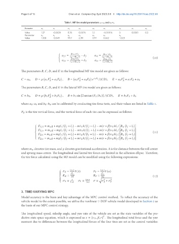
                                            Table 1. MF tire model parameters    0–   8 and    0–   6
                 Parameter     0       1         2      3         4      5         6        7        8
                 Value      1.37    -0.0039   8.78   0.0076    5.1    -0.00016  0        0.0001   0.3
                 Parameter     0       1         2      3         4      5         6
                 Value      1.388   -0.049    99.7   2,311     8.97   0.662     -1,323


                                        (
                                                        +                     −       
                                                   =   −                =
                                                     −        /2           −        /2                 (10)
                                                   =          +         −                =          −       
                                                      +        /2          +        /2
               The parameters   ,   ,   , and    in the longitudinal MF tire model are given as follows:


                                                      2
                                                                                   2
                                  2
                  =    0 ,     =       1    +    2       ,     =    3    +    4             5        /(    ),     =    6    +    7       +    8


               The parameters   ,   ,   , and    in the lateral MF tire model are given as follows:

                                  2
                  =    0 ,     =       1    +    2       ,     =    3 sin [2 arctan (      /   4 )] /(    ),     =    5       +    6
                                    
               where    0–   8 and    0–   6 can be calibrated by conducting tire force tests, and their values are listed in Table 1.
                     is the tire vertical force, and the vertical force of each tire can be expressed as follows:


                                                                         ¤
                                     =          +           /       +       −   ¤      ℎ/       +       −   (   +   )      ℎ      /             +      
                        
                        
                        
                                                                       ¤
                                      =          +           /       +       −   ¤      ℎ/       +       +   (   +   )      ℎ      /             +      
                                                                                                       (11)
                                                                         ¤
                                   =          +           /       +       +   ¤      ℎ/       +       −   (   +   )      ℎ      /             +      
                        
                        
                                                                        ¤
                                   =          +           /       +       +   ¤      ℎ/       +       +   (   +   )      ℎ      /             +      
               where       denotes tire mass, and    denotes gravitational acceleration. ℎ is the distance between the roll center
               and sprung mass center. The longitudinal and lateral tire forces are limited in the adhesion ellipse. Therefore,
               the tire force calculated using the MF model can be modified using the following expressions:
                                               =  |      |    (  )        =  |      |    (  )
                                        
                                                                      
                                                                         
                                                 =                   =                                 (12)
                                                                         
                                                                  q
                                                         tan         2    2
                                                =         =      =     +   
                                               1+        1+                
               3. TIME-VARYING MPC
               Model accuracy is the basis and key advantage of the MPC control method. To reflect the accuracy of the
               vehicle model to the extent possible, we utilize the nonlinear 7-DOF vehicle model developed in Section 2 as
               the basis of our MPC control strategy.


               The longitudinal speed, sideslip angle, and yaw rate of the vehicle are set as the state variables of the pre-
                                                                        
               dictive state space equation, which is expressed as    = [      ,   ,   ] . The longitudinal total force and the yaw
               moment due to differences between the longitudinal forces of the four tires are set as the control variables:
   35   36   37   38   39   40   41   42   43   44   45