
Page 157 - Read Online
P. 157
Wang et al. Microstructures 2023;3:2023036 https://dx.doi.org/10.20517/microstructures.2023.27 Page 5 of 12
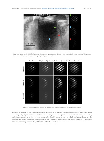
Figure 1. A virtual bright-field TEM image of the indented Mg specimen, along with the selected diffraction patterns. The patterns
shown on the right generally decrease in “quality” going down the column.
Figure 2. Selected diffraction patterns processed using brightness, contrast, and gamma adjustments.
patterns. However, as the clip limit increased, the radii of all diffraction spots also increased, including those
with originally high intensity, which became even brighter. In comparison to conventional image processing
techniques described in the previous paragraph, CLAHE better preserves a dark background and avoids
over-saturation in the originally bright spots while allowing weak diffraction spots to be well-illuminated
without sacrificing the overall quality of the diffraction pattern.