
Page 148 - Read Online
P. 148
Page 16 of 31 Chen et al. Microstructures 2023;3:2023025 https://dx.doi.org/10.20517/microstructures.2023.12
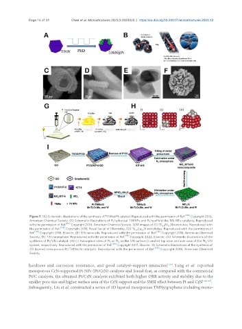
Figure 7. (A) Schematic illustrations of the synthesis of TiNiN@Pt catalyst. Reproduced with the permission of Ref. [109] Copyright 2016,
American Chemical Society. (B) Schematic illustrations of Pt/spherical TiN NPs and Pt/scaffold-like TiN NTs catalysts, Reproduced
with the permission of Ref. [110] Copyright 2016, American Chemical Society. SEM images of (C) Ti Ni N nanotubes. Reproduced with
0.9 0.1
the permission of Ref. [124] . Copyright 2018, Royal Social of Chemistry, (D) Ti Cu N nanoflakes. Reproduced with the permission of
0.9 0.1
Ref. [116] Copyright 2018, Elsevier, (E) TiN nanorods. Reproduced with the permission of Ref. [110] . Copyright 2016, American Chemical
Society, (F) TiN nanosphere. Reproduced with the permission of Ref. [119] Copyright 2022, Elsevier. (G) Schematic illustrations of the
synthesis of Pt/VN catalyst. (H) (i) Adsorption sites of Pt or Pt on the VN surface (ii and iii) top view and side view of the Pt -VN
1 6 6
system, respectively. Reproduced with the permission of Ref. [126] Copyright 2017, Elsevier. (I) Schematic illustrations of the synthesis of
[130]
2D layered mesoporous Pt/TMNs/G catalysts. Reproduced with the permission of Ref. . Copyright 2016, American Chemical
Society.
hardness and corrosion resistance, and good catalyst-support interaction . Yang et al. reported
[127]
mesoporous CrN-supported Pt NPs (Pt/CrN) catalysts and found that, as compared with the commercial
Pt/C catalysts, the obtained Pt/CrN catalysts exhibited both higher ORR activity and stability due to the
smaller pore size and higher surface area of the CrN support and the SMSI effect between Pt and CrN [128,129] .
Subsequently, Liu et al. constructed a series of 2D layered mesoporous TMNs/graphene including mono-