
Page 24 - Read Online
P. 24
Zhang et al. Microstructures 2023;3:2023010 https://dx.doi.org/10.20517/microstructures.2022.39 Page 9 of 12
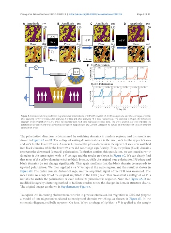
Figure 4. Domain switching and ionic migration characterizations of CIPS-IPS crystal. (A-D) The amplitude and phase images of initial,
after applying -6 V/+6 V bias, after applying -6 V bias and after applying +6 V bias, respectively. The scale bar is 1.5 μm. (E) Schematic
diagram of ion migration in CIPS under tip electric field. Red balls represent copper ions. The white and blue arrows indicate the
polarization direction and the electric field direction, respectively. (F) Current-voltage(I-V) curves at different scan rates in different
polarization areas.
The polarization direction is determined by switching domains in random regions, and the results are
shown in Figure 4A and B. The voltage of writing domain is shown in the inset, -6 V for the upper 1/3 area
and +6 V for the lower 2/3 area. As a result, most of the yellow domains in the upper 1/3 area were switched
into black domains, while the lower 2/3 area did not change significantly. Thus, the yellow (black) domains
represent the downward (upward) polarization. To further confirm this speculation, we continued to write
domains in the same region with -6 V voltage, and the results are shown in Figure 4C. We can clearly find
that most of the yellow domain switch to black domain, while the original non-polarization IPS phase and
black domains do not change significantly. This again confirms that the black domain corresponds to
upward polarization. We then applied a +6 V voltage at the same region, and the result is shown in
Figure 4D. The entire domain did not change, and the amplitude signal of the PFM was weakened. The
mean value was only 2/3 of the original amplitude in the CIPS phase. This means that a voltage of +6 V is
not able to switch the polarization or even reduce its piezoelectric response. Note that Figure 4A-D are
modified images by clustering method to facilitate readers to see the changes in domain structure clearly.
The original images are shown in Supplementary Figure 8.
To explain this interesting phenomenon, we refer to previous studies on ion migration in CIPS and propose
a model of ion migration-mediated nonreciprocal domain switching, as shown in Figure 4E. In the
schematic diagram, red balls represent Cu ions. When a voltage of tip bias -6 V is applied to the sample