
Page 136 - Read Online
P. 136
Prescott et al. Vessel Plus 2019;3:13 I http://dx.doi.org/10.20517/2574-1209.2018.70 Page 7 of 10
A B
Figure 6. Maximum principal stress (MPa) contour plot for mitral valve at peak diastole without MitraClip: (A) aerial view; (B) isometric view
A B
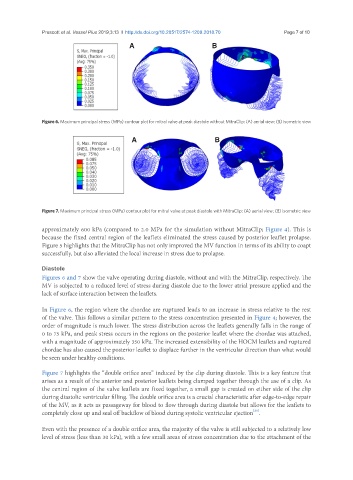
Figure 7. Maximum principal stress (MPa) contour plot for mitral valve at peak diastole with MitraClip: (A) aerial view; (B) isometric view
approximately 600 kPa (compared to 2.0 MPa for the simulation without MitraClip; Figure 4). This is
because the fixed central region of the leaflets eliminated the stress caused by posterior leaflet prolapse.
Figure 5 highlights that the MitraClip has not only improved the MV function in terms of its ability to coapt
successfully, but also alleviated the local increase in stress due to prolapse.
Diastole
Figures 6 and 7 show the valve operating during diastole, without and with the MitraClip, respectively. The
MV is subjected to a reduced level of stress during diastole due to the lower atrial pressure applied and the
lack of surface interaction between the leaflets.
In Figure 6, the region where the chordae are ruptured leads to an increase in stress relative to the rest
of the valve. This follows a similar pattern to the stress concentration presented in Figure 4; however, the
order of magnitude is much lower. The stress distribution across the leaflets generally falls in the range of
0 to 75 kPa, and peak stress occurs in the regions on the posterior leaflet where the chordae was attached,
with a magnitude of approximately 350 kPa. The increased extensibility of the HOCM leaflets and ruptured
chordae has also caused the posterior leaflet to displace further in the ventricular direction than what would
be seen under healthy conditions.
Figure 7 highlights the “double orifice area” induced by the clip during diastole. This is a key feature that
arises as a result of the anterior and posterior leaflets being clamped together through the use of a clip. As
the central region of the valve leaflets are fixed together, a small gap is created on either side of the clip
during diastolic ventricular filling. The double orifice area is a crucial characteristic after edge-to-edge repair
of the MV, as it acts as passageway for blood to flow through during diastole but allows for the leaflets to
[20]
completely close up and seal off backflow of blood during systolic ventricular ejection .
Even with the presence of a double orifice area, the majority of the valve is still subjected to a relatively low
level of stress (less than 30 kPa), with a few small areas of stress concentration due to the attachment of the