


Page 114 - Read Online
P. 114
Page 16 of 24                                                          Yu et al. Soft Sci. 2026, 6, 19


               distributed iterative calculation during the solution. Mesh and time step: free tetrahedral meshes are used for
               both the solid and fluid, and refined at the gripper and fluid boundaries; the time step is 0.01 ms, and the
               relative residual of the nonlinear solver is 10 . In terms of model verification, the reliability and accuracy of
                                                    -6
               the established numerical model in describing the magnetically driven deformation and dynamic response of
               the gripper were verified by comparing the displacement amplitude and motion time of the gripper in the
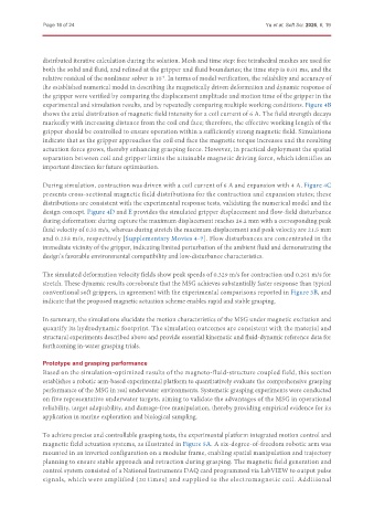
               experimental and simulation results, and by repeatedly comparing multiple working conditions. Figure 4B
               shows the axial distribution of magnetic field intensity for a coil current of 6 A. The field strength decays
               markedly with increasing distance from the coil end face; therefore, the effective working length of the
               gripper should be controlled to ensure operation within a sufficiently strong magnetic field. Simulations
               indicate that as the gripper approaches the coil end face the magnetic torque increases and the resulting
               actuation force grows, thereby enhancing grasping force. However, in practical deployment the spatial
               separation between coil and gripper limits the attainable magnetic driving force, which identifies an
               important direction for future optimization.


               During simulation, contraction was driven with a coil current of 6 A and expansion with 4 A. Figure 4C
               presents cross-sectional magnetic field distributions for the contraction and expansion states; these
               distributions are consistent with the experimental response tests, validating the numerical model and the
               design concept. Figure 4D and E provides the simulated gripper displacement and flow-field disturbance
               during deformation: during capture the maximum displacement reaches 26.2 mm with a corresponding peak
               fluid velocity of 0.33 m/s, whereas during stretch the maximum displacement and peak velocity are 21.5 mm
               and 0.258 m/s, respectively [Supplementary Movies 4-7]. Flow disturbances are concentrated in the
               immediate vicinity of the gripper, indicating limited perturbation of the ambient fluid and demonstrating the
               design’s favorable environmental compatibility and low-disturbance characteristics.

               The simulated deformation velocity fields show peak speeds of 0.329 m/s for contraction and 0.261 m/s for
               stretch. These dynamic results corroborate that the MSG achieves substantially faster response than typical
               conventional soft grippers, in agreement with the experimental comparisons reported in Figure 3B, and
               indicate that the proposed magnetic actuation scheme enables rapid and stable grasping.

               In summary, the simulations elucidate the motion characteristics of the MSG under magnetic excitation and
               quantify its hydrodynamic footprint. The simulation outcomes are consistent with the material and
               structural experiments described above and provide essential kinematic and fluid-dynamic reference data for
               forthcoming in-water grasping trials.

               Prototype and grasping performance
               Based on the simulation-optimized results of the magneto-fluid-structure coupled field, this section
               establishes a robotic arm-based experimental platform to quantitatively evaluate the comprehensive grasping
               performance of the MSG in real underwater environments. Systematic grasping experiments were conducted
               on five representative underwater targets, aiming to validate the advantages of the MSG in operational
               reliability, target adaptability, and damage-free manipulation, thereby providing empirical evidence for its
               application in marine exploration and biological sampling.

               To achieve precise and controllable grasping tests, the experimental platform integrated motion control and
               magnetic field actuation systems, as illustrated in Figure 5A. A six-degree-of-freedom robotic arm was
               mounted in an inverted configuration on a modular frame, enabling spatial manipulation and trajectory
               planning to ensure stable approach and retraction during grasping. The magnetic field generation and
               control system consisted of a National Instruments DAQ card programmed via LabVIEW to output pulse
               signals, which were amplified (20 times) and supplied to the electromagnetic coil. Additional

