


Page 113 - Read Online
P. 113
Yu et al. Soft Sci. 2026, 6, 19                                                  Page 15 of 24


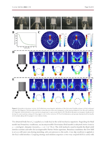
               Figure 4. Simulation of gripper motion. (A) Preliminary experimental validation of the fabricated flexible gripper (cylindrical target
               capture); (B) Magnetic field strength distribution along the axis of the electromagnetic coil at varying distances from the coil’s end face;
               (C) Magnetic field distribution cross-section during gripper’s capture and stretch; (D) Fluid field dynamics and gripper displacement
               during the capture phase, along with the gripper’s own motion velocity; (E) Fluid field dynamics and gripper displacement during the
               stretch phase, along with the gripper’s own motion velocity.

               The obtained body force f  is applied as a body load to the solid mechanics equations. Regarding the fluid
                                     m
               model and boundary conditions, an incompressible Newtonian fluid model is adopted (water density
               ρ = 1,000 kg/m , dynamic viscosity μ = 1.01 × 10  Pa·s). The ALE method is used to handle the fluid-solid
                           3
                                                        -3
               interface motion and solve the incompressible Navier-Stokes equations. Boundary conditions: the flow field
               is set as a still water area during modeling, with zero pressure at the outlet. A no-slip condition is applied at
               the fluid-solid interface. Coupling strategy and solution sequence: a two-way coupled MFSI is used, with

