
Page 93 - Read Online
P. 93
Kim et al. Soft Sci 2023;3:16 https://dx.doi.org/10.20517/ss.2023.07 Page 5 of 30
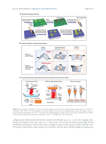
Figure 2. (A) Schematic illustration of the mechanically-guided assembly process. (Reproduced with permission from Ref. [63] .
©
Copyright 2019. WILEY-VCH Verlag GmbH & Co. KGaA, Weinheim); (B) structural design through origami and kirigami methods.
©
(Reproduced with permission from Ref. [239] . Copyright 2021. AIP Publishing); (C) light-based, photocurable material-based, and direct
©
ink-based 3D printing (Reproduced with permission from Ref. [240] . Copyright 2016. Springer Nature).
configurations. Both methods divide thin materials into flexible areas (i.e., a crease for origami, and a
linkage for kirigami) and rigid areas (i.e., a thin panel). The panels normally remain rigid during
deformation and energy is stored in the crease or linkage (as shown in the top row of Figure 2B). However,
if the panel is deformable, elastic energy can be stored in both the panel and the linkage, providing more