
Page 311 - Read Online
P. 311
Page 4 of 6 Lutter et al. Mini-invasive Surg 2020;4:36 I http://dx.doi.org/10.20517/2574-1225.2020.15
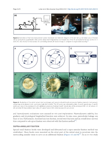
Figure 3. Illustration of the force measurement system developed: (a) schematic diagram of the test set-up; (b) lateral view of the test
set-up during force quantification after mitral valved stent implantation; (c) frontal view of the FS connected to the NC via the CE. S:
stent; NC: neo-chords; FS: force sensor; CE: connecting element; B: fixation bridge; C: computer for digital data recording [10]
Figure 4. Illustration of the mitral valved stent prototypes with apical and additional sub-annular fixation elements (red arrows),
comprising atrial element (LA), ventricular body (LV) and BV. The AF points are indicated by dots. A and B: apical view; C and D:
ventricular view of the prototype SA with additional subannular fixation; E and F: lateral view of the prototype SA12. LA: left atrium; LV:
left ventricle; BV: bioprosthetic heart valve; AF: apical fixation; MA: mitral annulus; SA: sub-annular
and haemodynamic evaluations were assessed 60 min post implantation. Haemodynamic stability, low
gradients and physiological longitudinal function were achieved. In nine cases, paravalvular leakage was
trace or less. Furthermore, decreased ejection fraction, several stent fractures and an overall lower survival
[11]
time compared to sole apical fixation were observed with this fixation method .
SUPRA-ANNULAR FIXATION
Special small fixation hooks were developed and fabricated and a supra-annular fixation method was
established. These hooks were mounted on the atrial part of the mitral stent to penetrate into the
[10]
surrounding annular tissue to serve as an additional fixation [Figure 5A and B] . In an in vivo study