


Page 30 - Read Online
P. 30
Zhang et al. J Mater Inf 2024;4:34  https://dx.doi.org/10.20517/jmi.2024.64     Page 23 of 28


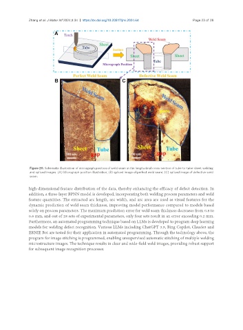
                Figure 20. Schematic illustration of micrograph position of weld seam in the longitudinal cross-section of tube-to-tube-sheet welding
                and spliced images. (A) Micrograph position illustration; (B) spliced image of perfect weld seam; (C) spliced image of defective weld
                seam.

               high-dimensional feature distribution of the data, thereby enhancing the efficacy of defect detection. In
               addition, a three-layer BPNN model is developed, incorporating both welding process parameters and weld
               feature quantities. The extracted arc length, arc width, and arc area are used as visual features for the
               dynamic prediction of weld seam thickness, improving model performance compared to models based
               solely on process parameters. The maximum prediction error for weld seam thickness decreases from 0.8 to
               0.6 mm, and out of 28 sets of experimental parameters, only four sets result in an error exceeding 0.2 mm.
               Furthermore, an automated programming technique based on LLMs is developed to program deep learning
               models for welding defect recognition. Various LLMs including ChatGPT 3.5, Bing Copilot, Claude3 and
               ERNIE Bot are tested for their application in automated programming. Through the technology above, the
               program for image stitching is programmed, enabling unsupervised automatic stitching of multiple welding
               microstructure images. The technique results in clear and wide-field weld images, providing robust support
               for subsequent image recognition processes.

