Page 116 - Read Online
P. 116

Peng et al. Intell Robot 2022;2(3):298­312  I http://dx.doi.org/10.20517/ir.2022.27  Page 300


                      b i                               - 1                 D  di P  Synchronous   Power plant
                                                        i R  governors  turbines    generator
                          ACE
                     +       i                        +  -     1       1   +  -       1
                               Scheduler  Network  K i                                               i f D
                                                                                      +
                                                                      +
                     +                                       1 sT+  gi  1 sT ti  -  D sM i
                                                 gain         D  vi P  D P mi    D P tiei
                                                                                           N
                                                                                          å  T
                                                                                   Tie line   ij
                                                                                         j= 1, j i ¹  N
                                                                                                å  ij T f D
                                                                                          +    j= 1, j i ¹  j
                                                                                   p
                                                                                  2 /s       -
                  Networked LFC System
                                                                                              Other areas
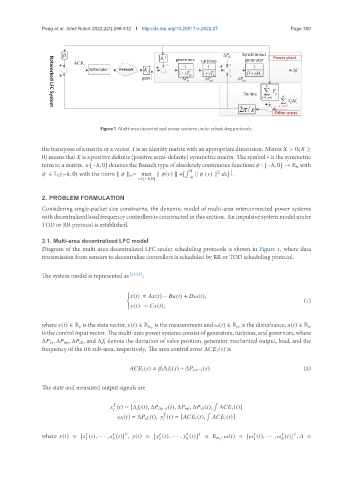
                                   Figure 1. Multi-area decentralized power systems under scheduling protocols.
               the transpose of a matrix or a vector.    is an identity matrix with an appropriate dimension. Matrix    > 0(   ≥
               0) means that    is a positive definite (positive semi-definite) symmetric matrix. The symbol ∗ is the symmetric
               term in a matrix.   [−ℎ, 0] denotes the Banach type of absolutely continuous functions    : [−ℎ, 0] → R    with
                                                                ¯  0           1
                                                                          2
                                                                      ·
                ·                                                  k    (  ) k     ] 2 .
                  ∈ L 2 (−ℎ, 0) with the norm k    k    = max k   (  ) k +[  −ℎ
                                                  ∈[−ℎ,0]
               2. PROBLEM FORMULATION
               Considering single-packet size constraints, the dynamic model of multi-area interconnected power systems
               with decentralized load frequency controllers is constructed in this section. An impulsive system model under
               TOD or RR protocol is established.


               2.1. Multi­area decentralized LFC model
               Diagram of the multi-area decentralized LFC under scheduling protocols is shown in Figure 1, where data
               transmission from sensors to decentralize controllers is scheduled by RR or TOD scheduling protocol.


               The system model is represented as [23,25] :


                                            (
                                             ¤   (  ) =     (  ) −     (  ) +     (  ),
                                                                                                       (1)
                                               (  ) =     (  ),


               where   (  ) ∈ R    is the state vector,   (  ) ∈ R        is the measurement and   (  ) ∈ R    is the disturbance,   (  ) ∈ R   
               is the control input vector. The multi-area power systems consist of generators, turbines, and governors, where
               Δ        , Δ        , Δ       , and Δ       denote the deviation of valve position, generator mechanical output, load, and the
               frequency of the     ℎ sub-area, respectively. The area control error           (  ) is


                                                       (  ) =       Δ       (  ) + Δ         −   (  ).  (2)


               The state and measured output signals are

                                                                         ¯
                                         
                                         (  ) = [Δ       (  ), Δ         −   (  ), Δ        , Δ        (  ),            (  )]
                                         
                                                                       ¯
                                                          
                                               (  ) = Δ        (  ),    (  ) = [          (  ),            (  )]
                                                          
                                                                                                      
               where   (  ) = [   (  ), · · · ,    (  )] ,   (  ) = [   (  ), · · · ,    (  )]  ∈ R       ,   (  ) = [   (  ), · · · ,    (  )] ,    =
                              1                        1                              1           
   111   112   113   114   115   116   117   118   119   120   121