
Page 96 - Read Online
P. 96
Page 91 Li et al. Intell Robot 2021;1(1):84-98 I http://dx.doi.org/10.20517/ir.2021.06
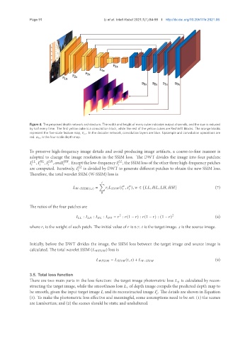
Figure 4. The proposed depth network architecture. The width and height of every cube indicates output channels, and the size is reduced
by half every time. The first yellow cube is a convolution block, while the rest of the yellow cubes are ResNeXt blocks. The orange blocks
represent the five-scale feature map, ×. In the decoder network, convolution layers are blue. Upsample and convolution operations are
red. × is the four-scale depth map.
To preserve high-frequency image details and avoid producing image artifacts, a coarse-to-fine manner is
adopted to change the image resolution in the SSIM loss. The DWT divides the image into four patches:
, , , . Except the low-frequency , the SSIM loss of the other three high-frequency patches
are computed. Iteratively, is divided by DWT to generate different patches to obtain the new SSIM loss.
Therefore, the total wavelet SSIM (W-SSIM) loss is
Õ
− ( , ) = ( , ), ∈ { , , , } (7)
0
The ratios of the four patches are
2 2
: : : = : (1 − ) : (1 − ) : (1 − ) (8)
where is the weight of each patch. The initial value of is 0.7. is the target image. is the source image.
Initially, before the DWT divides the image, the SSIM loss between the target image and source image is
calculated. The total wavelet SSIM ( ) loss is
(9)
= ( , ) + −
3.5. Total loss function
There are two main parts in the loss function: the target image photometric loss is calculated by recon-
structing the target image, while the smoothness loss of depth image compels the predicted depth map to
be smooth, given the input target image and its reconstructed image . The details are shown in Equation
(3). To make the photometric loss effective and meaningful, some assumptions need to be set: (1) the scenes
are Lambertian; and (2) the scenes should be static and unsheltered.