
Page 50 - Read Online
P. 50
Page 128 Tong et al. Intell Robot 2024;4:125-45 I http://dx.doi.org/10.20517/ir.2024.08
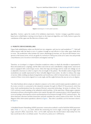
Figure 1. Block diagram of robot system operation.
algorithm. Section 4 gives the results of the validation experiments. Section 5 designs a gamified scenario-
based active rehabilitation training scheme based on the improved algorithm, and finally, Section 6 gives the
conclusions of this paper and the direction of future work.
2. ROBOTIC DEVICE MODELLING
Upper-limb rehabilitation robots are divided into two categories: end-traction and exoskeleton [33] . End-pull
robots interact with the hand or arm of a patient through an end-effector to drive other upper limb joints
to move. The exoskeleton robot imitates the human physiological structure, and the joint distribution corre-
sponds to the human joints, which can guide the movement of all human joints at the same time and provide
comprehensive joint movement information and targeted training [10] .
Therefore, we developed a 5-degree-of-freedom exoskeleton robot, in which the shoulder is represented by
three articulated motor couplings, and the elbow and wrist are each controlled by a single motor. Each motor
joint is equipped with a joint torque sensor, where the large arm linkage and the small arm linkage are set
as adjustable structures in order to adapt to the arm length of the patient. The shoulder joints of upper limb
exoskeletons are usually represented by three vertically aligned rotary joints. In order to enhance the range
of motion while avoiding mechanical singularities and interference with the human body, our shoulder joint
consists of three rotary joints aligned at an acute angle, and the angles between the axes are set as 60 degrees.
The robot hardware device adopts an industrial computer as the robot control system operation platform, and
the motor controller is connected to the industrial computer through the EtherCAT bus protocol, which has
better clock synchronisation than the common Ethernet connection technology. In terms of software, Twin-
CAT3 software is used, running on the industrial control machine. At the same time, CSharp upper computer
interaction software is developed to achieve data transfer through ADS communication; Unity3D gamification
scenetechnologyisdevelopedtoachievesynchronisationofmovementsthroughTCP/IPcommunication. The
above hardware selection and data interaction methods constitute the control system of this robot. The block
diagram of the robot system operation is shown in Figure 1. The robot is modelled, and the structure is shown
in Figure 2.
A Modified Denavit-Hartenberg (MDH) parameter construction method is used to build the MDH parameter
table [Table 1]. −1, −1, , and denote the connecting rod torsion angle, connecting rod length, joint
angle, and joint offset, respectively. Row of the table represents the transformation relationship from the
base coordinate to the 0 coordinate system. The units of and are in millimetres.