Page 47 - Read Online
P. 47

Page 6 of 15                     Cui et al. Complex Eng Syst 2023;3:3  I http://dx.doi.org/10.20517/ces.2022.57


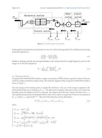
                                             Figure 2. The schematic diagram of energy flow.


               Inthis paper, thetransferfunctionfromtheyawvelocity      (  )tosteeringwheel      (  )isdefinedasthesteering
               sensitivity, expressed as

                                                       (  )        (  )   (  )
                                                       =                                               (10)
                                                         (  )    (  )         (  )
               Similar to steering road feel, the steering sensibility is also measured by the average frequency power in the
               range of 0-40 Hz and computed as
                                                       ¹           2
                                                   1        0         (  )
                                                   =                                                   (11)

                                                  2     0  0     ℎ (  )    =    

               2.2.3 Steering energy loss
               Compared with traditional HPS systems, energy consumption of EHPS systems is greatly reduced. However,
               it still has a huge potential for energy saving. The schematic diagram of the energy flow of the EHPS system is
               shown in Figure 2.

               The total energy of the steering system is supplied by the battery. One part of the energy is supplied to the
               ECU,and the energy loss is denoted as      −        . The other part is supplied to the drive motor, which drives the
               hydraulic pump according to the ECU command. The energy loss of the drive motor is denoted as      −        .
               The hydraulic pump pumps the hydraulic oil into rotary valve, and the energy losses of the two are denoted as
                    −         and      −        , respectively [9,14] . Thus, the total energy loss can be calculated as


                                             =      −         +      −         +      −         +      −          (12)
               where

                                  2
                            2        
                     − loss =          +
               
                                  elec
               
               
                                 n  
                            30  +          k e n  
                     − loss =    r a +   −         (  )   
               
                             K        30
               
               
               
                                   ¤    2       ¤    2
                       − loss =        −                   +        +                   (     −       )
                         8      2     2           1
               
               
                                             3                    3
               
                                                                     
                     − loss =       +             +      −           
               
                               2  4                 2  4
                         8(         1)         8(         2)
               
               
                              (  )              
                    =     +     (  ) +
                                             
   42   43   44   45   46   47   48   49   50   51   52