
Page 57 - Read Online
P. 57
Kimbowa et al. Art Int Surg 2024;4:149-69 https://dx.doi.org/10.20517/ais.2024.20 Page 151
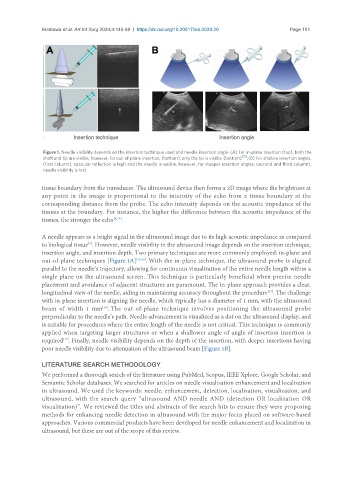
Figure 1. Needle visibility depends on the insertion technique used and needle insertion angle. (A) For in-plane insertion (top), both the
shaft and tip are visible; however, for out-of-plane insertion, (bottom), only the tip is visible (bottom) [15] ; (B) For shallow insertion angles,
(first column), specular reflection is high and the needle is visible; however, for steeper insertion angles, (second and third column),
needle visibility is lost.
tissue boundary from the transducer. The ultrasound device then forms a 2D image where the brightness at
any point in the image is proportional to the intensity of the echo from a tissue boundary at the
corresponding distance from the probe. The echo intensity depends on the acoustic impedance of the
tissues at the boundary. For instance, the higher the difference between the acoustic impedance of the
tissues, the stronger the echo [6,14] .
A needle appears as a bright signal in the ultrasound image due to its high acoustic impedance as compared
to biological tissue . However, needle visibility in the ultrasound image depends on the insertion technique,
[6]
insertion angle, and insertion depth. Two primary techniques are more commonly employed: in-plane and
out-of-plane techniques [Figure 1A] [15,16] . With the in-plane technique, the ultrasound probe is aligned
parallel to the needle’s trajectory, allowing for continuous visualization of the entire needle length within a
single plane on the ultrasound screen. This technique is particularly beneficial when precise needle
placement and avoidance of adjacent structures are paramount. The in-plane approach provides a clear,
longitudinal view of the needle, aiding in maintaining accuracy throughout the procedure . The challenge
[17]
with in-plane insertion is aligning the needle, which typically has a diameter of 1 mm, with the ultrasound
beam of width 1 mm . The out-of-plane technique involves positioning the ultrasound probe
[18]
perpendicular to the needle’s path. Needle advancement is visualized as a dot on the ultrasound display, and
is suitable for procedures where the entire length of the needle is not critical. This technique is commonly
applied when targeting larger structures or when a shallower angle of angle of insertion insertion is
[17]
required . Finally, needle visibility depends on the depth of the insertion, with deeper insertions having
poor needle visibility due to attenuation of the ultrasound beam [Figure 1B].
LITERATURE SEARCH METHODOLOGY
We performed a thorough search of the literature using PubMed, Scopus, IEEE Xplore, Google Scholar, and
Semantic Scholar databases. We searched for articles on needle visualization enhancement and localization
in ultrasound. We used the keywords: needle, enhancement, detection, localization, visualization, and
ultrasound, with the search query “ultrasound AND needle AND (detection OR localization OR
visualization)”. We reviewed the titles and abstracts of the search hits to ensure they were proposing
methods for enhancing needle detection in ultrasound with the major focus placed on software-based
approaches. Various commercial products have been developed for needle enhancement and localization in
ultrasound, but these are out of the scope of this review.