
Page 342 - Read Online
P. 342
Page 4 of 11 Zhang et al. Microstructures 2023;3:2023046 https://dx.doi.org/10.20517/microstructures.2023.57
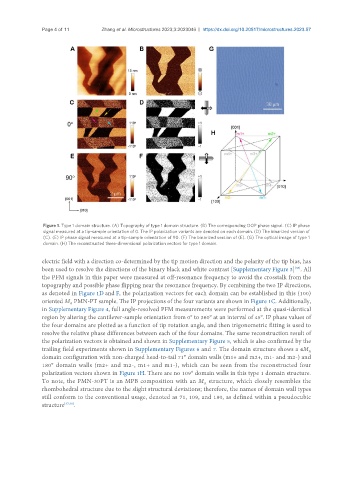
Figure 1. Type 1 domain structure. (A) Topography of type 1 domain structure. (B) The corresponding OOP phase signal. (C) IP phase
signal measured at a tip-sample orientation of 0. The IP polarization variants are denoted on each domain. (D) The binarized version of
(C). (E) IP phase signal measured at a tip-sample orientation of 90. (F) The binarized version of (E). (G) The optical image of type 1
domain. (H) The reconstructed three-dimensional polarization vectors for type 1 domain.
electric field with a direction co-determined by the tip motion direction and the polarity of the tip bias, has
[36]
been used to resolve the directions of the binary black and white contrast [Supplementary Figure 3] . All
the PFM signals in this paper were measured at off-resonance frequency to avoid the crosstalk from the
topography and possible phase flipping near the resonance frequency. By combining the two IP directions,
as denoted in Figure 1D and F, the polarization vectors for each domain can be established in this (100)
oriented M PMN-PT sample. The IP projections of the four variants are shown in Figure 1C. Additionally,
A
in Supplementary Figure 4, full angle-resolved PFM measurements were performed at the quasi-identical
region by altering the cantilever-sample orientation from 0° to 360° at an interval of 45°. IP phase values of
the four domains are plotted as a function of tip rotation angle, and then trigonometric fitting is used to
resolve the relative phase differences between each of the four domains. The same reconstruction result of
the polarization vectors is obtained and shown in Supplementary Figure 5, which is also confirmed by the
trailing field experiments shown in Supplementary Figures 6 and 7. The domain structure shows a 4M
A
domain configuration with non-charged head-to-tail 71° domain walls (m1+ and m2+, m1- and m2-) and
180° domain walls (m2+ and m2-, m1+ and m1-), which can be seen from the reconstructed four
polarization vectors shown in Figure 1H. There are no 109° domain walls in this type 1 domain structure.
To note, the PMN-30PT is an MPB composition with an M structure, which closely resembles the
A
rhombohedral structure due to the slight structural deviations; therefore, the names of domain wall types
still conform to the conventional usage, denoted as 71, 109, and 180, as defined within a pseudocubic
structure [37,38] .