
Page 130 - Read Online
P. 130
Page 12 of 19 Lee et al. Microstructures 2023;3:2023021 https://dx.doi.org/10.20517/microstructures.2023.08
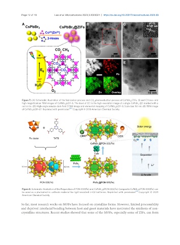
Figure 7. (A) Schematic illustration of the fabrication process and CO photoreduction process of CsPbBr /ZIFs. (B and C) Low- and
3
2
high-magnification TEM images of CsPbBr @ZIF-8. The inset of (C) is the high-resolution image of a single CsPbBr QD marked with a
3
3
red circle. (D) High-angle annular dark-field STEM image and elemental mapping of CsPbBr @ZIF-8. Scale bar: 50 nm. (E) TEM image
3
of CsPbBr @ZIF-67. Reprinted with permission [84] . Copyright © 2018 American Chemical Society.
3
Figure 8. Schematic illustration of the Preparation of PCN-333(Fe) and CsPbBr @PCN-333(Fe) Composite CsPbBr @PCN-333(Fe) can
3 3
be used as a photoelectric cathode material for light-assisted Li-O2 batteries. Reprinted with permission [91] . Copyright © 2021
American Chemical Society
So far, most research works on MOFs have focused on crystalline forms. However, limited processability
and deprived interfacial bonding between host and guest materials have motivated the synthesis of non-
crystalline structures. Recent studies showed that some of the MOFs, especially some of ZIFs, can form