


Page 34 - Read Online
P. 34
Page 16 of 22                  Andò et al. Vessel Plus 2023;7:15  https://dx.doi.org/10.20517/2574-1209.2023.26


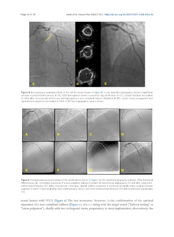
                Figure 4. Percutaneous revascularization of the calcific lesion shown in Figure 2B. In (A), baseline angiography shows a significant
                stenosis in proximal LAD (arrow). In (B), IVUS interrogation shows a concentric ring calcification. In (C), calcium fractures are evident
                at IVUS after Intravascular Lithotripsy and high-pressure non-compliant balloon dilatation. In (D), vessel lumen enlargement and
                optimal stent apposition are evident at IVUS. In (E) final angiographic result is shown.


                Figure 5. Percutaneous revascularization of the calcific lesion shown in Figure 1. In (A), baseline angiography is shown. After Rotational
                Atherectomy (B), incomplete expansion of a non-compliant balloon is evident at conventional angiography (C) and after using stent-
                enhancement features (D). After Intravascular Lithotripsy, optimal balloon expansion is confirmed along the entire calcified stenotic
                segment (E and F). Final result after stent optimization is shown with stent-enhancement features (G) and conventional angiography
                (H).


               vessel lumen with IVUS [Figure 4]. The key maneuver, however, is the confirmation of the optimal
               expansion of a non-compliant balloon [Figure 5], of a 1:1 sizing with the target vessel (“balloon testing” or
               “lesion palpation”), ideally with two orthogonal views, preparatory to stent implantation; alternatively, the

