


Page 126 - Read Online
P. 126
Page 16 of 57                                                       Zheng et al. Soft Sci. 2026, 6, 32


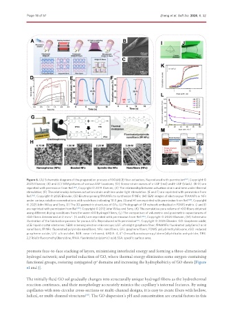
               Figure 6. (A) Schematic diagram of the preparation process of GO@LCE fiber actuators. Reproduced with permission [82] , Copyright ©
               2025 Elsevier; (B) and (C) SEM pictures of various LGF locations; (D) Stress-strain curves of c-LGF (red) and t-LGF (black). (B-D) are
               reprinted with permission from Ref. [83] , Copyright © 2019 Elsevier; (E) The relationship between actuation strain and time under thermal
               stimulation; (F) The relationship between actuation strain and time under light stimulation. (E and F) are reprinted with permission from
               Ref. [82] , Copyright © 2025 Elsevier; (G) Electrospinning fPAANFs to synthesize fPINFs; (H) SEM images of electrospun fPAANPs or NFs
               under various solution concentrations with scale bars indicating 10.0 μm. (G and H) are reprinted with permission from Ref. [84] , Copyright
               © 2025 John Wiley and Sons; (I) The 3D geometric structures of GFs; (J) Photograph of GF network embedded in PDMS matrix. (I and J)
               are reprinted with permission from Ref. [85] , Copyright © 2012 John Wiley and Sons; (K) The cumulative pore volume of rGO fibers obtained
               using different drying conditions from the same rGO hydrogel fibers; (L) The comparison of volumetric and gravimetric capacitances of
               rGO fibers determined at 2 mv·s . (K and L) are reprinted with permission from Ref. [86] , Copyright © 2020 Elsevier; (M) Schematic
                                     -1
               illustration of the fabrication process for porous GFs. Reproduced with permission [87] . Copyright © 2025 Elsevier. GO: Graphene oxide;
               LCE: liquid crystal elastomer; SEM: scanning electron microscope; LGF: ultralight graphene fiber; fPAANFs: fluorinated poly(amic) acid
               nanofibers; fPINFs: fluorinated polyimide nanofibers; NFs: nanofibers; GFs: graphene fibers; PDMS: polydimethylsiloxane; rGO: reduced
               graphene oxide; UV: ultraviolet; NIR: near-infrared; 6FDA: 4,4′-(hexafluoroisopropylidene)diphthalic anhydride; TFB:
               2,2′-bis(trifluoromethyl)benzidine; fPAA: fluorinated poly(amic) acid; SSA: specific surface area.


               promote face-to-face stacking of layers, minimising interfacial energy and forming a three-dimensional
               hydrogel network; and partial reduction of GO, where thermal energy eliminates some oxygen-containing
               functional groups, restoring conjugated sp  domains and increasing the hydrophobicity of GO sheets [Figure
                                                  2
               6I and J].


               The initially fluid GO sol gradually changes into structurally unique hydrogel fibers as the hydrothermal
               reaction continues, and their morphology accurately mimics the capillary’s internal features. By using
               capillaries with non-circular cross-sections or multi-channel designs, it is easy to create fibers with hollow,
               helical, or multi-channel structures . The GO dispersion’s pH and concentration are crucial factors in this
                                             [85]

