
Page 9 - Read Online
P. 9
Kikuchi et al. Mini-invasive Surg 2024;8:8 https://dx.doi.org/10.20517/2574-1225.2023.88 Page 3 of 11
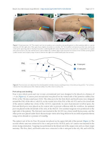
Figure 1. Patient position. (A) The original semi-prone position was created by placing the patient on the operating table in a prone
position with the right side of the upper body slightly elevated on a bolster; (B) The modified semi-prone position was created by
rotating the operating table in the hybrid position combining the left lateral decubitus and prone positions. Compared to the original
semi-prone position (A), the modified semi-prone position (B) created a larger space between the anterior chest and the operating table
(yellow arrows) and a slightly longer distance between the right arm and the fourth port (blue arrows).
Figure 2. Thoracoscopic port placement for robot-assisted minimally invasive esophagectomy in the semi-prone position. The numbers
indicate the intercostal spaces. PAL: Posterior axillary line; AAL: anterior axillary line.
Port set-up and docking
Four 8-mm robotic ports and one 12-mm conventional port were designed to be placed at a distance of
> 7 cm [Figure 2]. A camera port (second arm) was placed on the ventral side of the posterior axillary line
(PAL) of the 7th intercostal space (ICS). The other ports for the first, third, and fourth arms were designed
around the PAL of the 9th or 10th ICS, on the ventral side of the PAL of the 5th ICS, and on the dorsal side
of the anterior axillary line (AAL) of the 3rd ICS, respectively. In cases of prominent vertebral spurs, the
first and third ports were placed on the ventral side to prevent collisions with the vertebras. An assistant
port was placed on the dorsal side of the AAL at the 5th ICS. Two assistant surgeons were positioned on the
right side of the patient. The first port was inserted at the 7th ICS via a direct small thoracotomy, and the
other ports were placed under direct thoracoscopic vision after lung deflation by an artificial pneumothorax
using carbon dioxide at a pressure of 8 mmHg.
The patient cart of the da Vinci Xi system was placed on the upper left side of the patient [Figure 3]. The
second robotic arm was connected to the 8-mm port at the 7th ICS, and a 30° camera was inserted in the
down-facing orientation. Targeting was performed at the dorsal end of the azygos vein arch as a basic target
anatomy. The first, third, and fourth arms were connected to the 8-mm port at the 9th, 5th, and 3rd ICSs,