
Page 10 - Read Online
P. 10
Pecoraro et al. Mini-invasive Surg 2024;8:25 https://dx.doi.org/10.20517/2574-1225.2023.134 Page 3 of 12
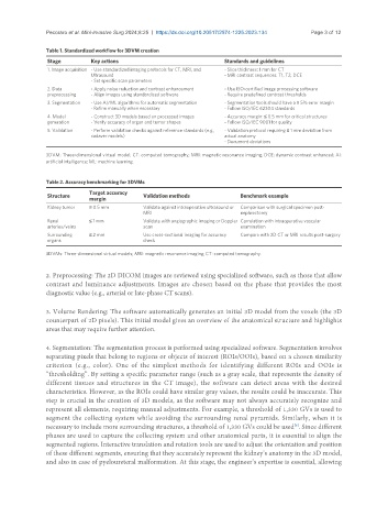
Table 1. Standardized workflow for 3DVM creation
Stage Key actions Standards and guidelines
1. Image acquisition - Use standardized imaging protocols for CT, MRI, and - Slice thickness: 1 mm for CT
Ultrasound - MRI contrast sequences: T1, T2, DCE
- Set specific scan parameters
2. Data - Apply noise reduction and contrast enhancement - Use ISO-certified image processing software
preprocessing - Align images using standardized software - Require predefined contrast thresholds
3. Segmentation - Use AI/ML algorithms for automatic segmentation - Segmentation tools should have a ≤ 5% error margin
- Refine manually when necessary - Follow ISO/IEC 62304 standards
4. Model - Construct 3D models based on processed images - Accuracy margin: ≤ 0.5 mm for critical structures
generation - Verify accuracy of organ and tumor shapes - Follow ISO/IEC 9001 for quality
5. Validation - Perform validation checks against reference standards (e.g., - Validation protocol requiring ≤ 1 mm deviation from
cadaver models) actual anatomy
- Document deviations
3DVM: Three-dimensional virtual model; CT: computed tomography; MRI: magnetic resonance imaging; DCE: dynamic contrast enhanced; AI:
artificial intelligence; ML: machine learning.
Table 2. Accuracy benchmarking for 3DVMs
Structure Target accuracy Validation methods Benchmark example
margin
Kidney tumor ≤ 0.5 mm Validate against intraoperative ultrasound or Comparison with surgical specimen post-
MRI nephrectomy
Renal ≤ 1 mm Validate with angiographic imaging or Doppler Correlation with intraoperative vascular
arteries/veins scan examination
Surrounding ≤ 2 mm Use cross-sectional imaging for accuracy Compare with 2D CT or MRI results post-surgery
organs check
3DVMs: Three-dimensional virtual models; MRI: magnetic resonance imaging; CT: computed tomography.
2. Preprocessing: The 2D DICOM images are reviewed using specialized software, such as those that allow
contrast and luminance adjustments. Images are chosen based on the phase that provides the most
diagnostic value (e.g., arterial or late-phase CT scans).
3. Volume Rendering: The software automatically generates an initial 3D model from the voxels (the 3D
counterpart of 2D pixels). This initial model gives an overview of the anatomical structure and highlights
areas that may require further attention.
4. Segmentation: The segmentation process is performed using specialized software. Segmentation involves
separating pixels that belong to regions or objects of interest (ROIs/OOIs), based on a chosen similarity
criterion (e.g., color). One of the simplest methods for identifying different ROIs and OOIs is
“thresholding”. By setting a specific parameter range (such as a gray scale, that represents the density of
different tissues and structures in the CT image), the software can detect areas with the desired
characteristics. However, as the ROIs could have similar gray values, the results could be inaccurate. This
step is crucial in the creation of 3D models, as the software may not always accurately recognize and
represent all elements, requiring manual adjustments. For example, a threshold of 1,330 GVs is used to
segment the collecting system while avoiding the surrounding renal pyramids. Similarly, when it is
necessary to include more surrounding structures, a threshold of 1,330 GVs could be used . Since different
[6]
phases are used to capture the collecting system and other anatomical parts, it is essential to align the
segmented regions. Interactive translation and rotation tools are used to adjust the orientation and position
of these different segments, ensuring that they accurately represent the kidney’s anatomy in the 3D model,
and also in case of pyeloureteral malformation. At this stage, the engineer’s expertise is essential, allowing