
Page 7 - Read Online
P. 7
Page 108 Calderoni et al. J Surveill Secur Saf 2020;1:106-18 I http://dx.doi.org/10.20517/jsss.2019.01
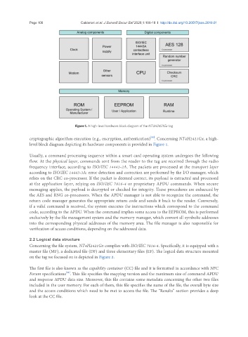
Figure 1. A high-level hardware block diagram of the NT4H2421Gx tag
[21]
cryptographic algorithm execution (e.g., encryption, authentication) . Concerning NT4H2421Gx, a high-
level block diagram depicting its hardware components is provided in Figure 1.
Usually, a command processing sequence within a smart card operating system undergoes the following
flow. At the physical layer, commands sent from the reader to the tag are received through the radio
frequency interface, according to ISO/IEC 14443-2A. The packets are processed at the transport layer
according to ISO/IEC 14443-3A: error detection and correction are performed by the I/O manager, which
relies on the CRC co-processor. If the packet is deemed correct, its payload is extracted and processed
at the application layer, relying on ISO/IEC 7816-4 or proprietary APDU commands. When secure
messaging applies, the payload is decrypted or checked for integrity. These procedures are enhanced by
the AES and RNG co-processors. When the APDU manager is not able to recognize the command, the
return code manager generates the appropriate return code and sends it back to the reader. Conversely,
if a valid command is received, the system executes the instructions which correspond to the command
code, according to the APDU. When the command implies some access to the EEPROM, this is performed
exclusively by the file management system and the memory manager, which convert all symbolic addresses
into the corresponding physical addresses of the memory area. The file manager is also responsible for
verification of access conditions, depending on the addressed data.
2.2 Logical data structure
Concerning the file system, NT4H2421Gx complies with ISO/IEC 7816-4. Specifically, it is equipped with a
master file (MF), a dedicated file (DF) and three elementary files (EF). The logical data structure mounted
on the tag we focused on is depicted in Figure 2.
The first file is also known as the capability container (CC) file and it is formatted in accordance with NFC
[22]
Forum specifications . This file specifies the mapping version and the maximum size of command APDU
and response APDU data size. Moreover, this file contains some metadata concerning the other two files
included in the user memory. For each of them, this file specifies the name of the file, the overall byte size
and the access conditions which need to be met to access the file. The “Results” section provides a deep
look at the CC file.