
Page 104 - Read Online
P. 104
Mooraj et al. J Mater Inf 2023;3:4 https://dx.doi.org/10.20517/jmi.2022.41 Page 29 of 45
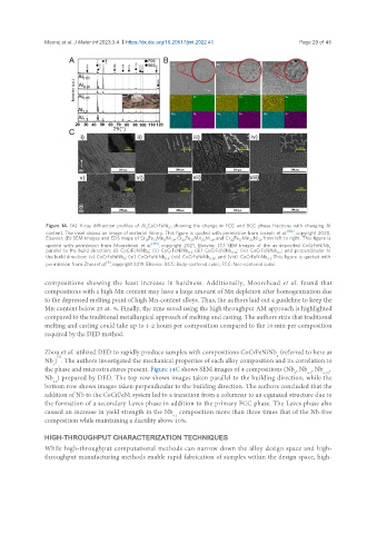
Figure 14. (A) X-ray diffraction profiles of Al CoCrFeNi showing the change in FCC and BCC phase fractions with changing Al
x 2.1
content. The inset shows an image of material library. This figure is quoted with permission from Joseph et al. [182] , copyright 2020,
Elsevier; (B) SEM images and EDS maps of Cr Fe Mn Ni , Cr Fe Mn Ni , and Cr Fe Mn Ni , from left to right. This figure is
11
39
19
31
28
17
42
21
20
23
20
29
[183]
quoted with permission from Moorehead et al. , copyright 2021, Elsevier; (C) SEM images of the as-deposited CoCrFeNiNb
x
parallel to the build direction: (i) CoCrFeNiNb ; (ii) CoCrFeNiNb ; (iii) CoCrFeNiNb ; (iv) CoCrFeNiNb ; and perpendicular to
0 0.1 0.15 0.2
the build direction: (v) CoCrFeNiNb ; (vi) CoCrFeNiNb ; (vii) CoCrFeNiNb ; and (viii) CoCrFeNiNb . This figure is quoted with
0 0.1 0.15 0.2
[9]
permission from Zhou et al. , copyright 2019, Elsevier. BCC: Body-centered cubic; FCC: face-centered cubic.
compositions showing the least increase in hardness. Additionally, Moorehead et al. found that
compositions with a high Mn content may have a large amount of Mn depletion after homogenization due
to the depressed melting point of high Mn-content alloys. Thus, the authors laid out a guideline to keep the
Mn-content below 25 at. %. Finally, the time saved using the high throughput AM approach is highlighted
compared to the traditional metallurgical approach of melting and casting. The authors state that traditional
melting and casting could take up to 1-2 hours per composition compared to the 10 min per composition
required by the DED method.
Zhou et al. utilized DED to rapidly produce samples with compositions CoCrFeNiNb (referred to here as
x
[9]
Nb ) . The authors investigated the mechanical properties of each alloy composition and its correlation to
x
the phase and microstructures present. Figure 14C shows SEM images of 4 compositions (Nb , Nb , Nb ,
0 0.1 0.15
Nb ) prepared by DED. The top row shows images taken parallel to the building direction, while the
0.2
bottom row shows images taken perpendicular to the building direction. The authors concluded that the
addition of Nb to the CoCrFeNi system led to a transition from a columnar to an equiaxed structure due to
the formation of a secondary Laves phase in addition to the primary FCC phase. The Laves phase also
caused an increase in yield strength in the Nb composition more than three times that of the Nb-free
0.2
composition while maintaining a ductility above 10%.
HIGH-THROUGHPUT CHARACTERIZATION TECHNIQUES
While high-throughput computational methods can narrow down the alloy design space and high-
throughput manufacturing methods enable rapid fabrication of samples within the design space, high-