
Page 18 - Read Online
P. 18
Page 324 Lei et al. Intell Robot 2022;2(4):31332 I http://dx.doi.org/10.20517/ir.2022.18
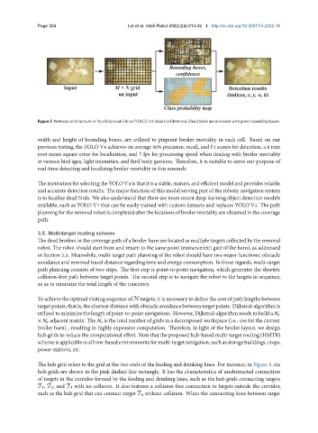
Figure 7. Network architecture of You Only Look Once (YOLO) V4 dead bird detector. Dead birds are enclosed with green bounding boxes.
width and height of bounding boxes, are utilized to pinpoint broiler mortality in each cell. Based on our
previous testing, the YOLO V4 achieves on average 90% precision, recall, and F1 scores for detection, 4.8 mm
root mean square error for localization, and 7 fps for processing speed when dealing with broiler mortality
at various bird ages, light intensities, and bird body gestures. Therefore, it is suitable to serve our purpose of
real-time detecting and localizing broiler mortality in this research.
ThemotivationforselectingtheYOLOV4 isthat itis astable, mature, and efficientmodel andprovides reliable
and accurate detection results. The major function of this model serving part of the robotic navigation system
is to localize dead birds. We also understand that there are more recent deep learning object detection models
available, such as YOLO V7 that can be easily trained with custom datasets and replaces YOLO V4. The path
planning for theremoval robotis completed after thelocations ofbroiler mortality are obtained in the coverage
path.
3.5. Multitarget routing scheme
The dead broilers in the coverage path of a broiler barn are located as multiple targets collected by the removal
robot. The robot should start from and return to the same point (entrance/exit gate of the barn), as addressed
in Section 2.3. Meanwhile, multi-target path planning of the robot should have two major functions: obstacle
avoidance and minimal travel distance regarding time and energy consumption. In those regards, multi-target
path planning consists of two steps. The first step is point-to-point navigation, which generates the shortest
collision-free path between target points. The second step is to navigate the robot to the targets in sequence,
so as to minimize the total length of the trajectory.
To achieve the optimal visiting sequence of N targets, it is necessary to define the cost of path lengths between
targetpoints, thatis, theshortestdistancewithobstacleavoidancebetweentargetpoints. Dijkstra’salgorithmis
utilizedtominimizethelengthofpoint-to-pointnavigations. However,Dijkstra’salgorithmneedstobuilda N
× N adjacent matrix. The N is the total number of grids in a decomposed workspace (i.e., 456 for the current
broiler barn) , resulting in highly expensive computation. Therefore, in light of the broiler layout, we design
hub grids to reduce the computational effort. Note that the proposed hub-based multi-target routing (HMTR)
schemeisapplicabletoallrow-basedenvironmentsformulti-targetnavigation,suchasstoragebuildings,crops,
power stations, etc.
The hub grid refers to the grid at the two ends of the feeding and drinking lines. For instance, in Figure 8, six
hub grids are shown in the pink dashed line rectangle. It has the characteristics of unobstructed connection
of targets in the corridor formed by the feeding and drinking lines, such as the hub grids connecting targets
T 1, T 2, and T 3 with no collision. It also features a collision-free connection to targets outside the corridor,
such as the hub grid that can connect target T 4 without collision. When the connecting lines between target