
Page 113 - Read Online
P. 113
Page 4 of 13 Cohen-Shohet et al. Plast Aesthet Res 2019;5:28 I http://dx.doi.org/10.20517/2347-9264.2019.030
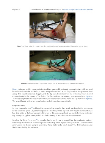
Figure 1. Left lower extremity traumatic wound on medial malleolus, after debridement and placement of external fixator
Figure 2. Immediately after V-Y advancement flap and closure. Tension free closure achieved over the wound
Figure 1 shows a healthy young male involved in a trauma. He sustained an open fracture with a wound
located over his medial malleolus. Closure was performed with a V-Y flap based on the posterior tibial
artery. This was identified via Doppler, and the flap was elevated only on the perforator, which allowed
increased mobility for closure of the defect. The flap is shown immediately post-operatively in Figure 2.
There was complete tension free closure. Finally, the wound is shown one-month post-operatively in Figure 3.
The wound healed without any complications and with good coverage distally.
Propeller flaps
[23]
In 1991, Hyakusoku et al. published the concept of the propeller flap, which was described for scar release
in the axilla and groin. Originally designed as a random pattern flap with a 90-degree arc of rotation, it
had little utility in the lower extremity. However, as this idea emerged and was blended with the perforator
flap concept, its application expanded to include coverage of wounds in the lower extremity.
[24]
Based on the Tokyo Consensus , a propeller flap is now defined as an axial flap that reaches the recipient
site through axial rotation. With a designated perforating vessel, a propeller flap indicates a flap that rotates
anywhere 90-180 degrees along its axis with a “large blade” and a “small blade”. The division between the
blades is marked by the perforator.