
Page 24 - Read Online
P. 24
Page 4 of 5 Chen et al. Plast Aesthet Res 2023;10:5 https://dx.doi.org/10.20517/2347-9264.2022.117
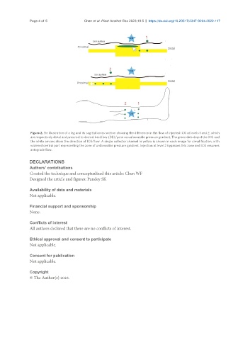
Figure 2. An illustration of a leg and its sagittal cross section showing the difference in the flow of injected ICG at levels 1 and 2, which
are respectively distal and proximal to dermal backflow (DB)/zone on unfavorable pressure gradient. The green dots depict the ICG and
the white arrows show the direction of ICG flow. A single collector channel in yellow is shown in each image for simplification, with
widened central part representing the zone of unfavorable pressure gradient. Injection at level 2 bypasses this zone and ICG resumes
antegrade flow.
DECLARATIONS
Authors’ contributions
Created the technique and conceptualized this article: Chen WF
Designed the article and figures: Pandey SK
Availability of data and materials
Not applicable.
Financial support and sponsorship
None.
Conflicts of interest
All authors declared that there are no conflicts of interest.
Ethical approval and consent to participate
Not applicable.
Consent for publication
Not applicable.
Copyright
© The Author(s) 2023.