
Page 395 - Read Online
P. 395
Page 6 of 9 Brandolini. Mini-invasive Surg 2020;4:45 I http://dx.doi.org/10.20517/2574-1225.2020.27
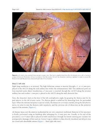
Figure 6. Left-sided video-assisted thoracoscopic surgery view. The thymic gland is freed from the left phrenic nerve with a harmonic
scalpel (Ultracision Harmonic; Johnson & Johnson, New Brunswick, NJ) and the dissection continues cephalad in order to access the
thoracic inlet and the previously dissected right side of the procedure
Step 2: left side
Right lung ventilation is re-initiated. The high-definition camera is inserted through a 5- or 10-mm port,
placed in the 5th ICS along the mid-axillary line within the inframammary fold. Two additional ports are
then inserted under direct visualisation; a 5-mm port is inserted through the 3rd ICS along the anterior
axillary line and another 5-mm port is placed in the 5th ICS along the mid-clavicular line.
Next, the dissection starts at the level of the left cardiophrenic angle, by grasping the thymus and the fat
pad anterior to the left phrenic nerve. The thymus gland is mobilized by dissecting from the pericardial
layer. When the retrosternal plane is opened widely, the dissection continues cranially along the left phrenic
nerve, in order to join the thoracic inlet superiorly, and the previous site of dissection on the posterior
aspect of the sternum [Figure 6].
All thymic tissue and the anterior mediastinal fat are now completely mobilized. Removal of the specimen
is finally performed using an Endobag after enlarging the 10-mm port site. Usually, at the end of the
procedure, a 24-F chest tube is placed in both hemithorces through the lowest existing port incision for
postoperative drainage of fluid and air. Correct lung re-inflation is then directly visualized and all port sites
are closed with absorbable sutures (Figure 7 - final right-side view).