
Page 11 - Read Online
P. 11
Lei et al. Intell Robot 2022;2(4):31332 I http://dx.doi.org/10.20517/ir.2022.18 Page 317
Figure 1. Illustration of simulated workspace based on a broiler barn. Blue lines are drinking lines, while grey lines are feeding lines. In total,
20,000 broilers are randomly distributed in the workspace.
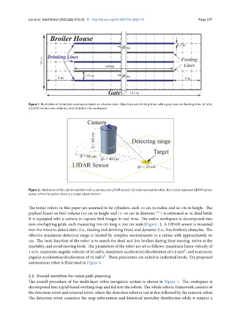
Figure 2. Illustration of the cylindrical robot with a camera and LIDAR sensor. Cylinder represents robot, dot circles represent LIDAR sensor
scans, while the yellow circle is a target (dead broiler).
The tested robots in this paper are assumed to be cylinders, each 20 cm in radius and 60 cm in height. The
payload based on bird volume (10 cm in height and 11–30 cm in diameter [33] ) is estimated as 30 dead birds.
It is equipped with a camera to capture bird images in real time. The entire workspace is decomposed into
non-overlapping grids, each measuring 200 cm long × 200 cm wide [Figure 1]. A LIDAR sensor is mounted
into the robot to detect static (i.e., feeding and drinking lines) and dynamic (i.e., live broilers) obstacles. The
effective maximum detection range is limited by complex environments to a radius with approximately 60
cm. The basic function of the robot is to search for dead and live broilers during their moving, arrive at the
mortality, and avoid moving birds. The parameters of the robot are set as follows: maximum linear velocity of
1 m/s, maximum angular velocity of 20 rad/s, maximum acceleration/deceleration of 0.2 m/s , and maximum
2
angular acceleration/deceleration of 50 rad/ . These parameters are suited to industrial levels. The proposed
2
autonomous robot is illustrated in Figure 2.
2.2. Overall workflow for robot path planning
The overall procedure of the multi-layer robot navigation system is shown in Figure 3. The workspace is
decomposed into a grid-based working map and fed into the robots. The whole robotic framework consists of
the detection robot and removal robot, where the detection robot is run at first followed by the removal robot.
The detection robot considers the map information and historical mortality distribution while it outputs a