
Page 12 - Read Online
P. 12
Liu et al. Intell Robot 2023;3(2):131-43 I http://dx.doi.org/10.20517/ir.2023.07 Page 135
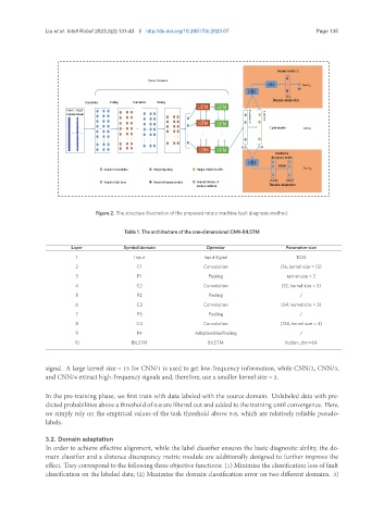
Figure 2. The structure illustration of the proposed rotary machine fault diagnosis method.
Table 1. The architecture of the one-dimensional CNN-BILSTM
Layer Symbol domain Operator Parameter size
1 Input Input Signal 1024
2 C1 Convolution (16, kernel size = 15)
3 P1 Pooling kernel size = 2
4 C2 Convolution (32, kernel size = 3)
5 P2 Pooling /
6 C3 Convolution (64, kernel size = 3)
7 P3 Pooling /
8 C4 Convolution (128, kernel size = 3)
9 P4 AdaptiveMaxPooling /
10 BILSTM BILSTM hidden_dim=64
signal. A large kernel size = 15 for CNN/1 is used to get low-frequency information, while CNN/2, CNN/3,
and CNN/4 extract high-frequency signals and, therefore, use a smaller kernel size = 3.
In the pre-training phase, we first train with data labeled with the source domain. Unlabeled data with pre-
dicted probabilities above a threshold of 0.8 are filtered out and added to the training until convergence. Here,
we simply rely on the empirical values of the task threshold above 0.8, which are relatively reliable pseudo-
labels.
3.2. Domain adaptation
In order to achieve effective alignment, while the label classifier ensures the basic diagnostic ability, the do-
main classifier and a distance discrepancy metric module are additionally designed to further improve the
effect. They correspond to the following three objective functions: (1) Minimize the classification loss of fault
classification on the labeled data; (2) Maximize the domain classification error on two different domains. 3)