Page 8 - Read Online
P. 8

Page 4 of 14                    Ma et al. Complex Eng Syst 2023;3:10  I http://dx.doi.org/10.20517/ces.2023.14


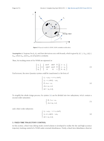
                                       Figure 1. Physical model of a WMR. WMR: wheeled mobile robot.


               Assumption2: Suppose the    1,    2, andtheir derivatives exist with bounds, which is given by |   1 | ≤    1   , |   2 | ≤
                  2  , where    1   and    2   are all positive constants.

               Then, the tracking errors of the WMR are expressed as


                                                   cos     sin   
                                                                0      −        
                                                                        
                                                =    − sin     cos     0       .                  (5)
                                                                       −       
                                                   0      0    1        
                                                                       −       
               Furthermore, the error dynamics system could be transformed in the form of
                                                 
                                                  ¤      =         −    +       cos      
                                                 
                                                 
                                                 
                                                 
                                                  ¤      =       sin       −        
                                                 
                                                 
                                                  
                                                   ¤                                                    (6)
                                                         =    −      
                                                 
                                                 
                                                 
                                                     ¤   =    1 +    1
                                                 
                                                 
                                                 
                                                 
                                                     ¤   =    2 +    2
                                                 
               To simplify the whole design process, the system (6) can be divided into two subsystems, which contain a
               second-order subsystem:
                                                     (
                                                        ¤
                                                              =    −      
                                                                                                        (7)
                                                           ¤   =    1 +    1
               and a third-order subsystem:
                                                  ¤      =         −    +       cos      
                                                 
                                                 
                                                  
                                                   ¤       =       sin       −                          (8)
                                                 
                                                 
                                                     ¤   =    2 +    2
                                                 
               3. FIXED-TIME TRAJECTORY CONTROL
               In this section, a fixed-time sliding mode control scheme is developed to realize the fast and high-accuracy
               trajectory tracking control of a WMR under external disturbances. Firstly, a fixed-time disturbance observer
   3   4   5   6   7   8   9   10   11   12   13