
Page 89 - Read Online
P. 89
Page 14 of 18 Guo et al. Intell Robot 2023;3(4):596-613 I http://dx.doi.org/10.20517/ir.2023.32
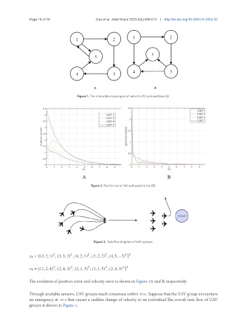
Figure 1. The interaction topologies of velocity (A) and position (B).
Figure 2. Position error (A) and speed error (B).
Figure 3. Task flow diagram of UAV groups.
0 = [(3, 2, 1) , (3, 3, 2) , (4, 2, 1) , (3, 2, 2) , (4, 5, −2) ]
0 = [(1, 2, 4) , (2, 4, 3) , (2, 1, 3) , (1, 1, 5) , (2, 4, 3) ]
The evolution of position error and velocity error is shown in Figure 2A and B, respectively.
Through available sensors, UAV groups reach consensus within 10 s. Suppose that the UAV group encounters
an emergency at 10 s that causes a sudden change of velocity in an individual.The overall task flow of UAV
groups is shown in Figure 3.