
Page 125 - Read Online
P. 125
Page 150 Boin et al. Intell Robot 2022;2(2):14567 I http://dx.doi.org/10.20517/ir.2022.11
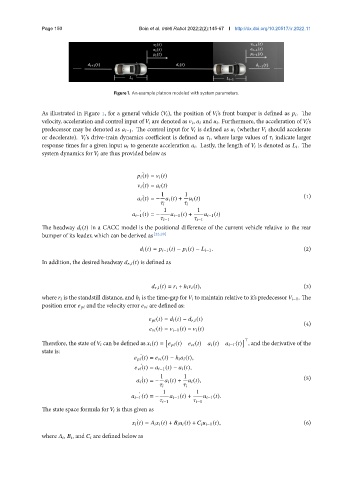
Figure 1. An example platoon modeled with system parameters.
As illustrated in Figure 1, for a general vehicle ( ), the position of ’s front bumper is defined as . The
velocity, acceleration and control input of are denoted as , and . Furthermore, the acceleration of ’s
predecessor may be denoted as −1. The control input for is defined as (whether should accelerate
or decelerate). ’s drive-train dynamics coefficient is defined as , where large values of indicate larger
response times for a given input to generate acceleration . Lastly, the length of is denoted as . The
system dynamics for are thus provided below as
¤
( ) = ( )
¤
( ) = ( )
1 1 (1)
¤
( ) = − ( ) + ( )
1 1
¤
−1 ( ) = − −1 ( ) + −1 ( )
−1 −1
The headway ( ) in a CACC model is the positional difference of the current vehicle relative to the rear
bumper of its leader, which can be derived as [22,29]
( ) = −1 ( ) − ( ) − −1 . (2)
In addition, the desired headway , ( ) is defined as
, ( ) = + ℎ ( ), (3)
where is the standstill distance, and ℎ is the time-gap for to maintain relative to it’s predecessor −1. The
position error and the velocity error are defined as:
( ) = ( ) − , ( )
(4)
( ) = −1 ( ) − ( )
[ ] >
Therefore, the state of can be defined as ( ) = ( ) ( ) ( ) −1 ( ) , and the derivative of the
state is:
¤
( ) = ( ) − ℎ ( ),
( ) = −1 ( ) − ( ),
¤
1 1 (5)
¤
( ) = − ( ) + ( ),
1 1
¤
−1 ( ) = − −1 ( ) + −1 ( ).
−1 −1
The state space formula for is thus given as
( ) = ( ) + ( ) + −1 ( ), (6)
¤
where , , and are defined below as